Subaru Legacy BN/BS (2015-2019) Service Manual: Assembly
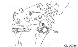
1. Clean the holes in the sliding surface between the clutch pedal and bushing, and apply grease. 2. Attach the clutch pedal pad, clutch pedal stopper, bushing A, torsion spring bushing, spacer and bushing to the clutch pedal. NOTE: Clean the inside of the bushings and apply grease before installing the spacer. 3. Attach the clutch pedal to the pedal bracket. Tightening torque: T: 30 N·m (3.1 kgf-m, 22.1 ft-lb)
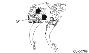
4. Install the assist bushing and torsion spring to the pedal assembly. NOTE: Before installing the torsion spring, apply grease to the assist bushing and torsion spring bushing. 5. Install the master cylinder to the pedal assembly. NOTE: Secure the push rod with a tape etc. to prevent it from falling off. Tightening torque: T: 18 N·m (1.8 kgf-m, 13.3 ft-lb)
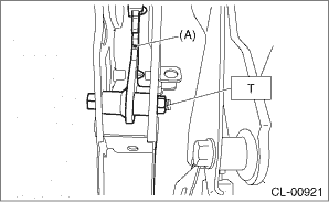
6. Secure the clevis pin with mounting clip. CAUTION: Always use a new clevis pin. NOTE: Before installing the clevis pin, apply grease.
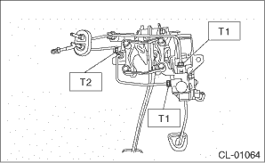
7. Attach the sensor harness, and connect the connector to the clutch stroke sensor. 8. Install the clutch switch. 9. Install the clutch damper to the pedal assembly, and connect the clutch pipe to the master cylinder. Tightening torque: T1: 15 N·m (1.5 kgf-m, 11.1 ft-lb) T2: 18 N·m (1.8 kgf-m, 13.3 ft-lb)
|
 Disassembly
1. Disconnect the clutch pipe from the master cylinder.2. Remove the clutch damper mounting nut from the pedal assembly, and disconnect the clutch pipe from the clamp.3. Remove the clutch switches.4. ...

Other materials:
Inspection mode procedure
It is possible to diagnose the DTC by performing the indicated inspection mode. After correcting the DTC, perform a necessary inspection mode and make sure that the function is resumed correctly and the DTC is recorded.1. INSPECTION MODE 1DTCItemNoteB1430IN-VEHICLE (POST EVAPORATOR) TEMPERATURE SENS ...
