Subaru Legacy BN/BS (2015-2019) Service Manual: Assembly
1. Install the forward clutch piston to forward clutch drum. NOTE: • Apply CVTF to the seal of forward clutch piston. • Insert it all the way to the end.
2. Install the return spring.
3. Install the forward clutch piston seal. NOTE: Apply CVTF to the sealing area of forward clutch piston seal.
4. Compress the return spring using the ST to install the snap ring.
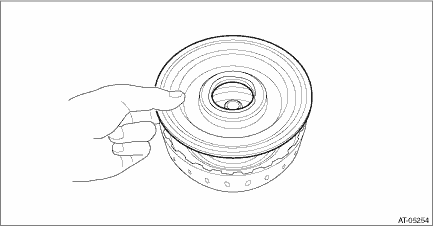
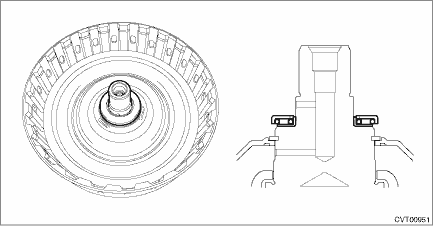
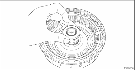
5. Install the thrust needle bearing. NOTE: Install the thrust needle bearing in the correct direction.
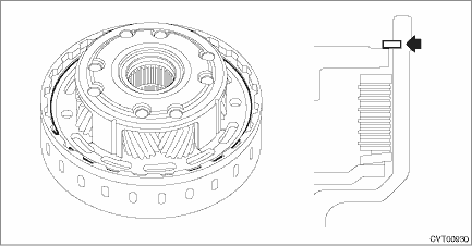
6. Install the snap ring.
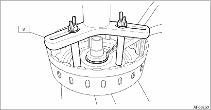
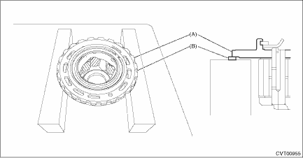
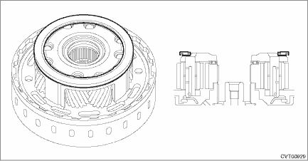
7. Measure the height “A” from the ST end surface to the snap ring of forward clutch drum using the ST on the surface plate. NOTE: • Measure while lifting the snap ring. • Place the measurement tool at the dent on ST upper side to measure.
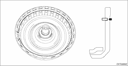
8. Measure height “B” from the ST end surface to the thrust needle bearing using the ST. NOTE: Place the measurement tool at the dent on ST upper side to measure.
9. Remove the snap ring.
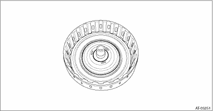
10. Place flat boards on the surface plate, and place the snap ring and then planetary carrier assembly overlapping neatly. NOTE: Carefully place them so that the most outer finished surface of planetary carrier assembly overlaps the snap ring.
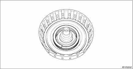
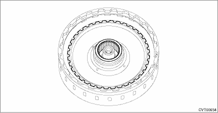
11. Install the thrust needle bearing. NOTE: Make sure to install in the right direction.
12. Install the sun gear. NOTE: Make sure to install in the right direction.
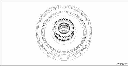
13. Install the forward clutch hub.
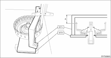
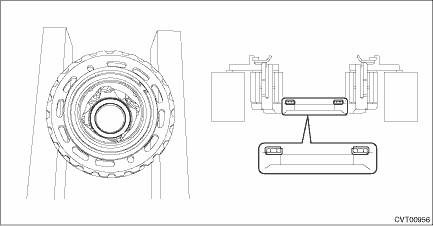
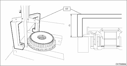
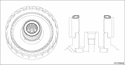
14. Using the ST, measure the height “C” from the ST end surface to the flat board with the snap ring placed on. NOTE: Place the measurement tool at the dent on ST upper side to measure.
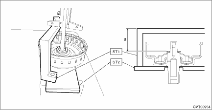
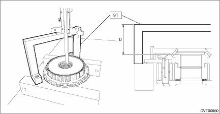
15. Using the ST, measure the height “D” from the ST end surface to the washer catch surface of the forward clutch hub. NOTE: Place the measurement tool at the dent on ST upper side to measure.
16. Obtain the thickness of washer using the values measured from step 7) to step 15). Calculation formula: T mm = (B − A) − (C − D) − (0.0 — 0.20) [T in = (B − A) − (C − D) − (0.0 — 0.008)] T: Washer thickness A: Height from the ST end surface to the snap ring of the forward clutch drum B: Height from the ST end surface to the thrust needle bearing C: Height from the ST end surface to the flat board with the snap ring placed on D: Height from the ST end surface to the washer catch surface of the forward clutch hub 0.0 — 0.20 mm (0.0 — 0.008 in): Clearance 17. Select the washer to meet the value “T” obtained from step 16).
18. Install the dish plate, drive plate, driven plate and retaining plate.
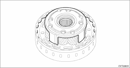
19. Install the planetary carrier assembly.
20. Install the snap ring.
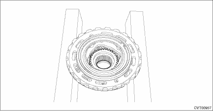
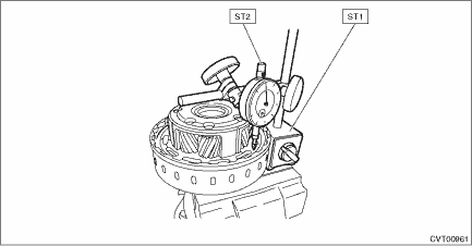
21. Hold the forward clutch drum on a vise, and set the ST.
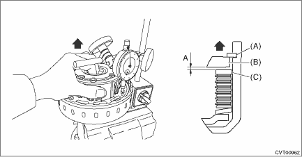
22. Lift the planetary carrier assembly, and read the value “A” indicated on the dial gauge. NOTE: Measure at four points with a 90° interval and calculate the average.
23. If the value “A” obtained from step 22) exceeds the limit for use, replace the drive plate and driven plate with new parts and select the retaining plate within the initial standard value. Initial standard: 1.2 — 1.6 mm (0.047 — 0.063 in) Limit thickness: 2.4 mm (0.09 in)
24. Remove the snap ring and the planetary carrier assembly. 25. Replace with the retaining plate selected in step 23) to install. 26. Install the thrust needle bearing. NOTE: Install the thrust needle bearing in the correct direction.
27. Install the washer selected in step 17).
28. Install the forward clutch hub.
29. Install the sun gear.
30. Install the thrust needle bearing. NOTE: Install the thrust needle bearing in the correct direction.
31. Install the planetary carrier assembly.
32. Install the snap ring.
33. Install the thrust needle bearing. NOTE: Install the thrust needle bearing in the correct direction.
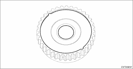
34. Install the thrust gear plate to the internal gear.
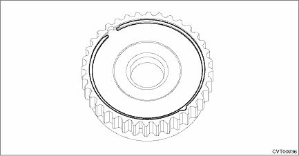
35. Install the snap ring.
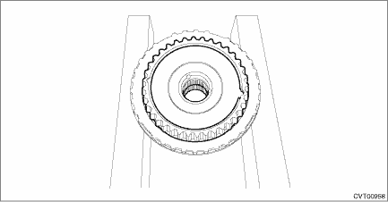
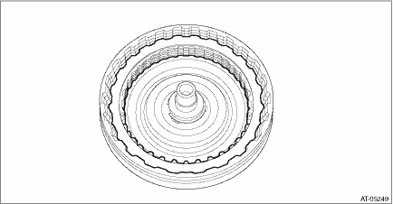
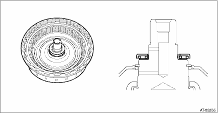
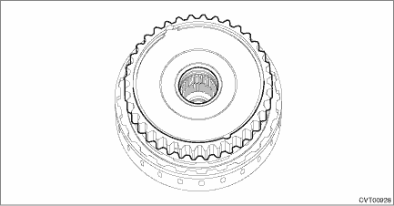
36. Install the internal gear assembly.
| ||||||||||||||||||||||||||||||||||||||||||||||||||||||||||
 Disassembly
1. Remove the internal gear assembly.2. Remove the snap ring from the internal gear assembly.3. Remove the thrust gear plate.4. Remove the thrust needle bearing.5. Remove the snap ring.6. Remove the p ...

Other materials:
Inspection
1. Check that the radiator does not have deformation, cracks or damage.2. Check that the hose has no cracks, damage or loose part.3. Remove the radiator cap, fill the radiator with engine coolant, and then install the radiator cap tester to the filler neck of radiator.4. Apply a pressure of 157 kPa ...
