Subaru Legacy BN/BS (2015-2019) Service Manual: Assembly
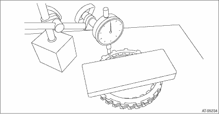
1. Place the dish plate, driven plate, drive plate and retaining plate neatly in this order on surface table. NOTE: Make sure of the direction of dish plate. 2. Set the dial gauge to retaining plate, and read its scale. NOTE: The value, which is read in the gauge at this time, is zero point. 3. Scale and record the weight “Z” of a flat board which will be put on retaining plate. NOTE: • Use a stiff board which does not bend against load as a flat board to be put on retaining plate. • Use a flat board weighing less than 130 N (13.3 kgf, 29.2 lb). 4. Put the flat board on retaining plate.
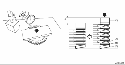
5. Using the following formula, calculate load “N”, a force of pressing with push/pull gauge. N = 130N (13.3 kgf, 29.2 lb) – Z 130 N (13.3 kgf, 29.2 lb) : Load applied to clutch plate Z: Flat board weight 6. Press the center of retaining plate by applying a force of “N” using push/pull gauge, and then measure and record the compression amount “A”. NOTE: Measure at four points with a 90° interval and calculate the average.
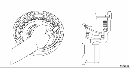
7. Install the dish plate, driven plate, drive plate, retaining plate and snap ring. NOTE: Make sure of the direction of dish plate. 8. Measure and record the clearance “B” between the retaining plate and snap ring. NOTE: Before measuring, press down the whole circumference of retaining plate using your finger.
9. Piston stroke calculation Calculate with A and B dimensions recorded before. If out of standard, replace with a new drive plate and adjust it within standard. S mm (in) = A + B S: Piston stroke A: Compression amount of drive plate and dish plate B: Clearance between retaining plate and snap ring Specification: 2.4 — 2.8 mm (0.094 — 0.11 in)
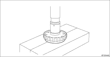
10. Press-fit the ball bearing into front driven shaft. NOTE: Use a new ball bearing.
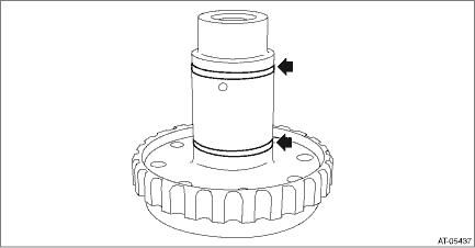
11. Install the seal ring to the front driven shaft. NOTE: • Install a new seal ring. • Apply CVTF to the seal rings.
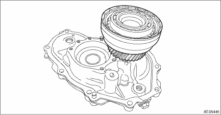
12. Install the front reduction driven shaft to the front reduction driven gear. 13. Install the front reduction driven gear assembly to converter case cover.
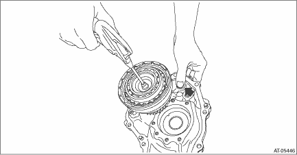
14. Apply compressed air intermittently to check the piston operation. NOTE: Hold the arrowed area with a finger.
| ||||||||||||||||||
 Disassembly
1. Remove the front reduction driven shaft from the front reduction driven gear.2. Remove the snap ring.3. Remove the retaining plate, drive plate, driven plate and dish plate.4. Remove the seal ring ...

Other materials:
Removal
CAUTION:If the engine oil is spilt over exhaust pipe or the under cover, wipe it off with cloth to avoid emission of smoke or causing a fire.1. Disconnect the ground terminal from battery sensor. NOTE2. Remove the under cover. Front Under Cover > REMOVAL3. Drain the engine oil. Engine Oil > REPLA ...
