Subaru Legacy BN/BS (2015-2019) Service Manual: Communication for initializing impossible
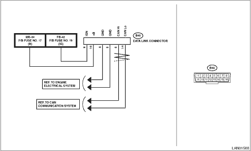
DIAGNOSIS: Subaru Select Monitor communication line is open or shorted. TROUBLE SYMPTOM: Not communicable with Subaru Select Monitor. WIRING DIAGRAM: CAN communication system CAN Communication System > WIRING DIAGRAM
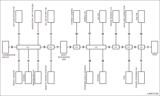
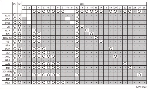
1. CHECK USING THE CHECK SHEET OF COMMUNICATION FOR INITIALIZING • Network diagram
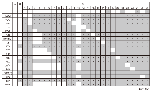
• Check sheet of communication for initializing
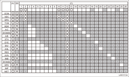
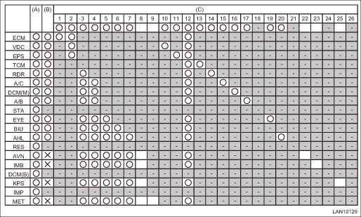
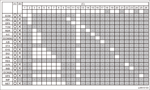
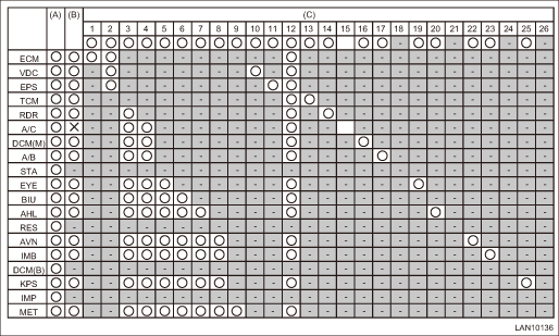
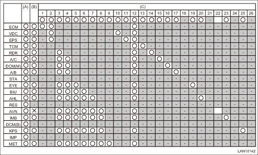
1. Module installation check (1) Write “-” marks in the field for installation check if the vehicle to be inspected does not have relevant module. (2) Write “-” marks in all blank fields on the same row that the “-” mark has filled in. NOTE: Example of writing Subaru Select Monitor > COMMUNICATION FOR INITIALIZING IMPOSSIBLE 2. Subaru Select Monitor communication initialization check (1) Write “ If the communication with all modules is not possible, go to 3). (2) Write “ (3) When at least one field in a column of wiring location is filled with the “ (4) Check the open circuit of the modules which have no “ (5) If the communication is not possible after checking all harnesses, check the module power supply line. (6) Replace the module if the power supply line is normal. NOTE: • Example of writing Subaru Select Monitor > COMMUNICATION FOR INITIALIZING IMPOSSIBLE • Inspection using the communication for initializing of Subaru Select Monitor cannot be used to diagnose the wiring location marked with “-”. Example of DTC data not received List of Diagnostic Trouble Code (DTC) > LIST should be used to identify the faulty portion. 3. Subaru Select Monitor communication initialization check (impossible to communicate with all modules) NOTE: If at least one module becomes possible to communicate, return to 2). (1) Check for the short circuit to ground. CAN Communication Circuit Check > INSPECTION If it is normal, go to the next. (2) Check for the short circuit to battery. CAN Communication Circuit Check > INSPECTION If it is normal, go to the next. (3) Perform the inspection for the resistance of 52 - or less (short between wires). CAN Communication Circuit Check > INSPECTION If it is normal, go to the next. (4) Check for the open circuit of network diagram No. 12 (data link connector). 2. EXAMPLE OF WRITING FOR THE CHECK SHEET OF COMMUNICATION FOR INITIALIZING • When No. 1 is open
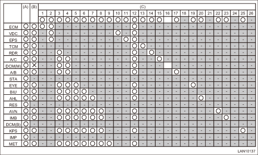
• When No. 2 is open
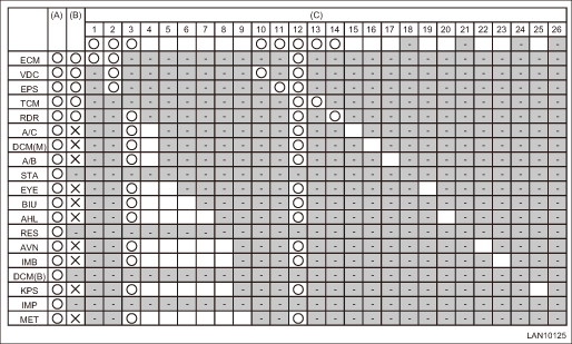
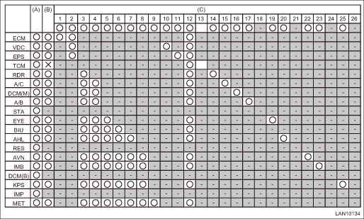
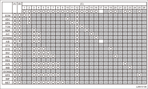
• When No. 3 is open
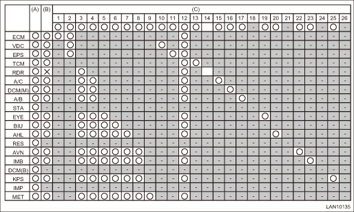
• When No. 4 is open
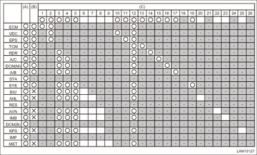
• When No. 5 is open
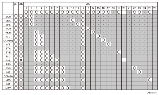
• When No. 6 is open
• When No. 7 is open
• When No. 8 is open
• When No. 9 is open
• When No. 10 is open
• When No. 11 is open
• When No. 12 is open NOTE: Perform inspection by referring to 3) communication initialization check (impossible to communicate with all modules). (There may be a malfunction other than open circuit)
• When No. 13 is open
• When No. 14 is open
• When No. 15 is open
• When No. 16 is open
• When No. 17 is open
• When No. 18 is open NOTE: This is the same as No. 21, No. 24 and No. 26, but it is possible to diagnose using examples of lost communication detection in each module. List of Diagnostic Trouble Code (DTC) > LIST
• When No. 19 is open
• When No. 20 is open
• When No. 21 is open NOTE: This is the same as No. 18, No. 24 and No. 26, but the remote engine starter does not operate while no DTC is detected.
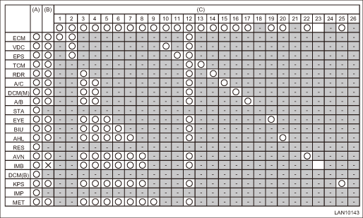
• When No. 22 is open
• When No. 23 is open
• When No. 24 is open NOTE: This is the same as No. 18, No. 21 and No. 26, but it is possible to diagnose using examples of lost communication detection in each module. List of Diagnostic Trouble Code (DTC) > LIST
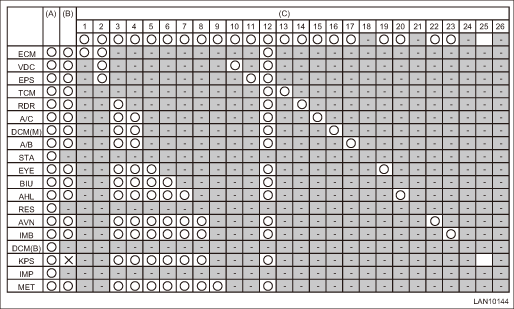
• When No. 25 is open
• When No. 26 is open NOTE: This is the same as No. 18, No. 21 and No. 24, but the impact sensor does not operate while no DTC is detected.
|
 ” marks in the field for communication initialization if the module succeeded in the communication for initializing with Select Monitor.
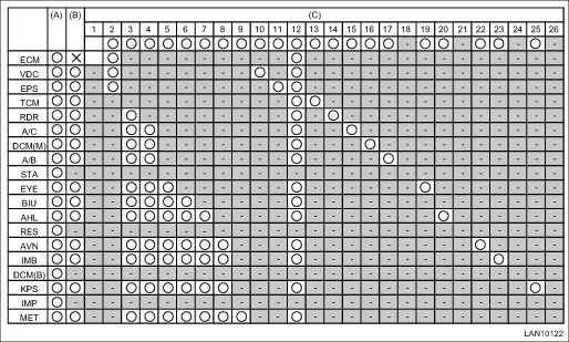


 Operation
For details of basic operations, refer to “Application help”. ...
Other materials:
Installation
1. Before installation, check the steering gearbox. Electric Power Steering Gearbox > INSPECTION2. Install the steering gearbox assembly by tightening the bolts through the stiffener to the specified torque.CAUTION:Be careful not to damage the steering gearbox assembly boot.Tightening torque:60 N&m ...
