Honda Civic manuals

Subaru Legacy BN/BS (2015-2019) Service Manual: Dtc b1572 imm circuit except antenna circuit

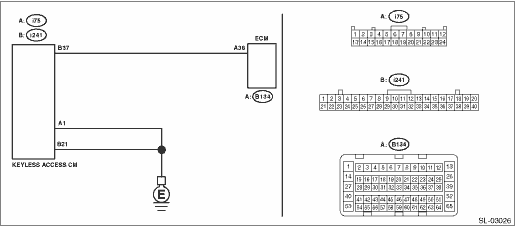
1. EXCEPT FOR C0 AND C5 MODELS

DTC DETECTING CONDITION:

Communication error between keyless access CM and ECM

TROUBLE SYMPTOM:

Engine will not start.

CAUTION:

For replacement procedure of keyless access CM and ECM, refer to the “REGISTRATION MANUAL FOR IMMOBILIZER” provided as a separate volume.

WIRING DIAGRAM:

NOTE:

For the coupling connector, refer to “WIRING SYSTEM”.

Keyless access with push button start system Keyless Access With Push Button Start System > WIRING DIAGRAM

STEPCHECKYESNO

1.CHECK GROUNDING POINT.

Check the grounding point of the engine ground and chassis ground.

Is there any looseness- Are there any foreign matters caught on the ground or contact surface- Are there any oil-soiled areas-

Remove the foreign matters, and tighten to the specified torque. Then start the engine, and check that the fault was removed. Check DTC Read Diagnostic Trouble Code (DTC), and when DTC B1572 is still displayed, Diagnostic Procedure with Diagnostic Trouble Code (DTC) > DTC B1572 IMM CIRCUIT EXCEPT ANTENNA CIRCUIT

Diagnostic Procedure with Diagnostic Trouble Code (DTC) > DTC B1572 IMM CIRCUIT EXCEPT ANTENNA CIRCUIT

2.CHECK CURRENT DATA.

1) Turn the ignition switch to ON.

2) Check the current data display of «Keyless access with push button start» using Subaru Select Monitor. Read Current Data

3) Display the next data. «Immobilizer» «Engine start» «Unlock confirmation»

Data

«Immobilizer» = «Unset»:

«Engine start» = «Engine start permission»:

«Unlock confirmation» = «Confirmed»:

Is the data displayed as described above-

Diagnostic Procedure with Diagnostic Trouble Code (DTC) > DTC B1572 IMM CIRCUIT EXCEPT ANTENNA CIRCUIT

Perform diagnostics with phenomenon. Diagnostics with Phenomenon > INSPECTION

3.CHECK CURRENT DATA.

Use the Subaru Select Monitor to check the current data of «Keyless access with push button start» when holding down the push button ignition switch while depressing the brake pedal (except for MT models) or the clutch pedal (MT models). Read Current Data

Data

«EGI code reception status» = «Reception»:

NOTE:

If «Reception» is displayed, the status changes to «Not yet received» in 10 seconds. When performing the check again, perform the check after turning the ignition to OFF.

Is the data displayed as described above-

Diagnostic Procedure with Diagnostic Trouble Code (DTC) > DTC B1572 IMM CIRCUIT EXCEPT ANTENNA CIRCUIT

Repair or replace the harness between keyless access CM and ECM.

4.CHECK WIRING HARNESS.

1) Turn the ignition switch to OFF.

2) Disconnect the keyless access CM connector and ECM connector.

3) Using a tester, measure the resistance between the keyless access CM connector and ECM.

Connector & terminal

(i241) No. 37 — (B134) No. 38:

Is the resistance less than 10 --

Diagnostic Procedure with Diagnostic Trouble Code (DTC) > DTC B1572 IMM CIRCUIT EXCEPT ANTENNA CIRCUIT

Repair or replace the open circuit of harness.

5.CHECK WIRING HARNESS.

Using a tester, measure the resistance between the keyless access CM connector and chassis ground.

Connector & terminal

(i75) No. 1 — Chassis ground:

(i241) No. 21 — Chassis ground:

Is the resistance less than 10 --

Diagnostic Procedure with Diagnostic Trouble Code (DTC) > DTC B1572 IMM CIRCUIT EXCEPT ANTENNA CIRCUIT

Repair or replace the open circuit of harness.

6.CHECK ECM.

1) Install the ECM from other normal operating vehicle (with push button start) which use same ECM to the vehicle to be diagnosed.

2) Perform ECM registration. Refer to the “REGISTRATION MANUAL FOR IMMOBILIZER” provided as a separate volume.

Is ECM registration finished- And does the engine start-

Replace the ECM. Engine Control Module (ECM) > REMOVAL Engine Control Module (ECM) > REMOVAL Install the ECM from other vehicle to the original vehicle.

Replace the keyless access CM. Keyless Access CM

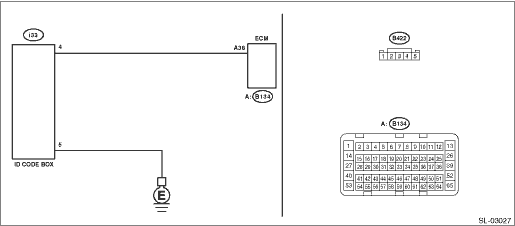
2. FOR C0 AND C5 MODELS

DTC DETECTING CONDITION:

Communication error between ID code box and ECM

TROUBLE SYMPTOM:

Engine will not start.

CAUTION:

For replacement procedure of ID code box and ECM, refer to “REGISTRATION MANUAL FOR IMMOBILIZER” provided as a separate volume.

WIRING DIAGRAM:

NOTE:

For the coupling connector, refer to “WIRING SYSTEM”.

Keyless access with push button start system Keyless Access With Push Button Start System > WIRING DIAGRAM

STEPCHECKYESNO

1.CHECK GROUNDING POINT.

Check the grounding point of the engine ground and chassis ground.

Is there any looseness- Are there any foreign matters caught on the ground or contact surface- Are there any oil-soiled areas-

Remove the foreign matters, and tighten to the specified torque. Then start the engine, and check that the fault was removed. Check DTC Read Diagnostic Trouble Code (DTC), and when DTC B1572 is still displayed, Diagnostic Procedure with Diagnostic Trouble Code (DTC) > DTC B1572 IMM CIRCUIT EXCEPT ANTENNA CIRCUIT

Diagnostic Procedure with Diagnostic Trouble Code (DTC) > DTC B1572 IMM CIRCUIT EXCEPT ANTENNA CIRCUIT

2.CHECK CURRENT DATA.

1) Turn the ignition switch to ON.

2) Check the current data display of «Keyless access with push button start» using Subaru Select Monitor. Read Current Data

3) Display the next data. «Immobilizer» «Engine start» «Unlock confirmation»

Data

«Immobilizer» = «Unset»:

«Engine start» = «Engine start permission»:

«Unlock confirmation» = «Confirmed»:

Is the data displayed as described above-

Diagnostic Procedure with Diagnostic Trouble Code (DTC) > DTC B1572 IMM CIRCUIT EXCEPT ANTENNA CIRCUIT

Perform diagnostics with phenomenon. Diagnostics with Phenomenon > INSPECTION

3.CHECK CURRENT DATA.

Use the Subaru Select Monitor to check the current data of «Keyless access with push button start» when holding down the push button ignition switch while depressing the brake pedal (except for MT models) or the clutch pedal (MT models). Read Current Data

Data

«EGI code reception status» = «Reception»:

NOTE:

If «Reception» is displayed, the status changes to «Not yet received» in 10 seconds. When performing the check again, perform the check after turning the ignition to OFF.

Is the data displayed as described above-

Diagnostic Procedure with Diagnostic Trouble Code (DTC) > DTC B1572 IMM CIRCUIT EXCEPT ANTENNA CIRCUIT

Repair or replace the harness between ID code box and ECM.

4.CHECK WIRING HARNESS.

1) Turn the ignition switch to OFF.

2) Disconnect the ID code box connector and the ECM connector.

3) Using a tester, measure the resistance between ID code box connector and ECM.

Connector & terminal

(i33) No. 4 — (B134) No. 38:

Is the resistance less than 10 --

Diagnostic Procedure with Diagnostic Trouble Code (DTC) > DTC B1572 IMM CIRCUIT EXCEPT ANTENNA CIRCUIT

Repair or replace the open circuit of harness.

5.CHECK WIRING HARNESS.

Using a tester, measure the resistance between ID code box connector and chassis ground.

Connector & terminal

(i33) No. 5 — Chassis ground:

Is the resistance less than 10 --

Diagnostic Procedure with Diagnostic Trouble Code (DTC) > DTC B1572 IMM CIRCUIT EXCEPT ANTENNA CIRCUIT

Repair or replace the open circuit of harness.

6.CHECK ECM.

1) Install the ECM from other normal operating vehicle (with push button start) which use same ECM to the vehicle to be diagnosed.

2) Perform ECM registration. Refer to the “REGISTRATION MANUAL FOR IMMOBILIZER” provided as a separate volume.

Is ECM registration finished- And does the engine start-

Replace the ECM. Engine Control Module (ECM) > REMOVAL Engine Control Module (ECM) > REMOVAL Install the ECM from other vehicle to the original vehicle.

Replace the ID code box. ID Code Box > NOTE

Dtc b1576 egi control module eeprom
DTC DETECTING CONDITION:• ECM malfunctioning• When the ROM in ECM was inaccessible during registration.TROUBLE SYMPTOM:Engine will not start.CAUTION:For replacement procedure of ECM, refer ...

Dtc b27a8 trunk/rear gate external antenna open
DTC DETECTING CONDITION:When open circuit occurs in the harness between keyless access CM and rear exterior antenna.TROUBLE SYMPTOM:Keyless access system does not function.(Unable to unlock with the r ...

Other materials:

Installation
1. Install the panel center LWR.2. Install the console box assembly.3. Install the cover assembly - front.4. Install the shift knob. (MT model)NOTE:For 6MT model, refer to “MT GEAR SHIFT LEVER” in “CS” section. MT Gear Shift Lever > INSTALLATION5. Install the ornament panel ...

© 2017-2024 Copyright www.sulegacy.com