1.CHECK POOR CONTACT OF CONNECTOR. Check if there is poor contact between VDCCM&H/U and ABS wheel speed sensor. | | | Diagnostic Procedure with Diagnostic Trouble Code (DTC) > DTC C1241 REAR LEFT ABS SENSOR CIRCUIT |
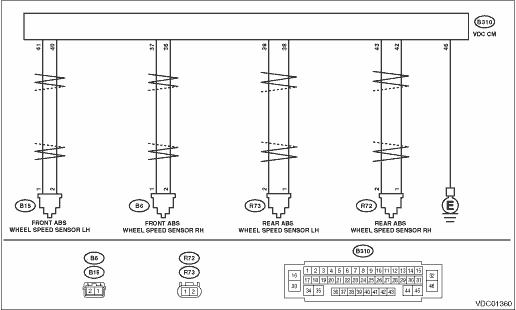
2.CHECK HARNESS CONNECTOR BETWEEN VDCCM&H/U AND ABS WHEEL SPEED SENSOR (CHECK FOR OPEN CIRCUIT). 1) Turn the ignition switch to OFF. 2) Disconnect the connector (B310) from the VDCCM&H/U. 3) Disconnect the connector from ABS wheel speed sensor. 4) Measure the resistance between VDCCM&H/U connector and ABS wheel speed sensor connector. Connector & terminal DTC C1211 (B310) No. 37 — (B6) No. 1:
(B310) No. 36 — (B6) No. 2: DTC C1221 (B310) No. 41 — (B15) No. 1:
(B310) No. 40 — (B15) No. 2: DTC C1231 (B310) No. 42 — (R72) No. 1:
(B310) No. 43 — (R72) No. 2: DTC C1241 (B310) No. 38 — (R73) No. 1:
(B310) No. 39 — (R73) No. 2: | Is the resistance less than 1 -- | Diagnostic Procedure with Diagnostic Trouble Code (DTC) > DTC C1241 REAR LEFT ABS SENSOR CIRCUIT | Repair the harness connector between VDCCM&H/U and ABS wheel speed sensor. |
3.CHECK GROUND SHORT OF HARNESS. Measure the resistance between VDCCM&H/U connector and chassis ground. Connector & terminal DTC C1211 (B310) No. 36 — Chassis ground: DTC C1221 (B310) No. 40 — Chassis ground: DTC C1231 (B310) No. 42 — Chassis ground: DTC C1241 (B310) No. 38 — Chassis ground: | Is the resistance 1 M- or more- | Diagnostic Procedure with Diagnostic Trouble Code (DTC) > DTC C1241 REAR LEFT ABS SENSOR CIRCUIT | Repair the harness connector between VDCCM&H/U and ABS wheel speed sensor. |
4.CHECK ABS WHEEL SPEED SENSOR POWER SUPPLY CIRCUIT. 1) Connect the VDCCM&H/U connector. 2) Connect the ABS wheel speed sensor connector. 3) Turn the ignition switch to ON. 4) Measure the voltage between ABS wheel speed sensor connector and chassis ground. Connector & terminal DTC C1211 (B6) No. 1 (+) — Chassis ground (−): DTC C1221 (B15) No. 1 (+) — Chassis ground (−): DTC C1231 (R72) No. 2 (+) — Chassis ground (−): DTC C1241 (R73) No. 2 (+) — Chassis ground (−): | | Diagnostic Procedure with Diagnostic Trouble Code (DTC) > DTC C1241 REAR LEFT ABS SENSOR CIRCUIT | Diagnostic Procedure with Diagnostic Trouble Code (DTC) > DTC C1241 REAR LEFT ABS SENSOR CIRCUIT |
5.CHECK VDCCM&H/U POWER SUPPLY CIRCUIT. 1) Turn the ignition switch to OFF. 2) Disconnect the VDCCM&H/U connector. 3) Turn the ignition switch to ON. 4) Measure the voltage between VDCCM&H/U connector terminals. Connector & terminal (B310) No. 5 (+) — (B310) No. 46 (−): (B310) No. 16 (+) — (B310) No. 46 (−): (B310) No. 33 (+) — (B310) No. 46 (−): | Is the voltage 10 — 15 V- | Diagnostic Procedure with Diagnostic Trouble Code (DTC) > DTC C1241 REAR LEFT ABS SENSOR CIRCUIT | Check the generator, battery and VDCCM&H/U power supply circuit. |
6.CHECK ABS WHEEL SPEED SENSOR SIGNAL. 1) Prepare an oscilloscope. 2) Check the ABS wheel speed sensor. Front ABS Wheel Speed Sensor > INSPECTION | Is the pattern the same waveform as shown in the figure- | Diagnostic Procedure with Diagnostic Trouble Code (DTC) > DTC C1241 REAR LEFT ABS SENSOR CIRCUIT | Replace the ABS wheel speed sensor. Front ABS Wheel Speed Sensor |
7.CHECK VDCCM&H/U. 1) Connect all connectors. 2) Perform the Clear Memory Mode. Clear Memory Mode 3) Perform the Inspection Mode. Inspection Mode 4) Read the DTC. Read Diagnostic Trouble Code (DTC) | Is the same DTC displayed- | Replace the VDCCM&H/U. VDC Control Module and Hydraulic Control Unit (VDCCM&H/U) | Diagnostic Procedure with Diagnostic Trouble Code (DTC) > DTC C1241 REAR LEFT ABS SENSOR CIRCUIT |
8.CHECK DETECTION OF OTHER DTCS FOR VDC. Read Diagnostic Trouble Code (DTC) | Is any other DTC displayed- | Perform the diagnosis according to DTC. List of Diagnostic Trouble Code (DTC) | Currently, it is normal. There may have been a poor contact in the harness and connector or a temporarily noise interference. |

 Dtc c1242 rear left abs sensor signal
 Dtc c1232 rear right abs sensor signal