Subaru Legacy BN/BS (2015-2019) Service Manual: Dtc p0032 a/f / o2 heater control circuit high bank 1 sensor 1
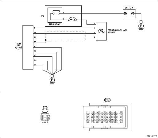
DTC DETECTING CONDITION: Immediately at fault recognition CAUTION: After servicing or replacing faulty parts, perform Clear Memory Mode Clear Memory Mode > OPERATION, and Inspection Mode Inspection Mode > PROCEDURE. WIRING DIAGRAM: • Engine Electrical System ENGINE TYPE FB (WITHOUT PUSH BUTTON START) Engine Electrical System > WIRING DIAGRAM • Engine Electrical System ENGINE TYPE FB (WITH PUSH BUTTON START) Engine Electrical System > WIRING DIAGRAM
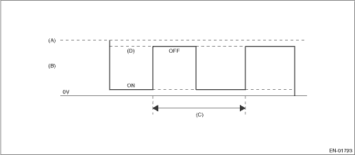
1. OUTLINE OF DIAGNOSIS Detect front oxygen (A/F) sensor heater open or short circuit. The front oxygen (A/F) sensor heater performs duty control, and the output terminal voltage at ON is 0 V, and the output terminal voltage at OFF is the battery voltage. Judge as NG when the terminal voltage remains High. 2. COMPONENT DESCRIPTION
3. EXECUTION CONDITION
4. GENERAL DRIVING CYCLE Perform the diagnosis continuously after the enable conditions have been established. 5. DIAGNOSTIC METHOD If the duration of time while the following conditions are met is longer than the time indicated, judge as NG.
Time Needed for Diagnosis: 2 seconds Malfunction Indicator Light Illumination: Illuminates as soon as a malfunction occurs. |
 Dtc p0037 a/f / o2 heater control circuit low bank 1 sensor 2
DTC DETECTING CONDITION:Detected when two consecutive driving cycles with fault occur.CAUTION:After servicing or replacing faulty parts, perform Clear Memory Mode Clear Memory Mode > OPERATION, and I ...
 Dtc p0031 a/f / o2 heater control circuit low bank 1 sensor 1
DTC DETECTING CONDITION:Immediately at fault recognitionCAUTION:After servicing or replacing faulty parts, perform Clear Memory Mode Clear Memory Mode > OPERATION, and Inspection Mode Inspection Mod ...
Other materials:
Installation
1. Clean the mating surface of converter case cover and converter case.2. Select the shim for front reduction drive gear. Front Reduction Drive Gear > ADJUSTMENT3. Apply CVTF to the shims and install on the bearing catch surface of the front reduction driven gear.4. Install the seal ring to convert ...
