Honda Civic manuals

Subaru Legacy BN/BS (2015-2019) Service Manual: Dtc p0037 a/f / o2 heater control circuit low bank 1 sensor 2

DTC DETECTING CONDITION:

Detected when two consecutive driving cycles with fault occur.

CAUTION:

After servicing or replacing faulty parts, perform Clear Memory Mode Clear Memory Mode > OPERATION, and Inspection Mode Inspection Mode > PROCEDURE.

WIRING DIAGRAM:

Engine Electrical System ENGINE TYPE FB (WITHOUT PUSH BUTTON START) Engine Electrical System > WIRING DIAGRAM

Engine Electrical System ENGINE TYPE FB (WITH PUSH BUTTON START) Engine Electrical System > WIRING DIAGRAM

STEPCHECKYESNO

1.CHECK POWER SUPPLY TO REAR OXYGEN SENSOR.

1) Turn the ignition switch to OFF.

2) Disconnect the connector from rear oxygen sensor.

3) Turn the ignition switch to ON.

4) Measure the voltage between rear oxygen sensor connector and engine ground.

Connector & terminal

(E25) No. 1 (+) — Engine ground (−):

Is the voltage 10 V or more-

Diagnostic Procedure with Diagnostic Trouble Code (DTC) > DTC P0037 A/F / O2 HEATER CONTROL CIRCUIT LOW BANK 1 SENSOR 2

Repair the power supply line. Or replace the main relay.

NOTE:

In this case, repair the following item:

Open circuit in harness between A/F, oxygen sensor relay connector and rear oxygen sensor connector

Poor contact of A/F, oxygen sensor relay connector

Poor contact of coupling connector

Malfunction of A/F, oxygen sensor relay

2.CHECK HARNESS BETWEEN ECM AND REAR OXYGEN SENSOR CONNECTOR.

1) Turn the ignition switch to OFF.

2) Disconnect the connector from ECM.

3) Measure the resistance between ECM connector and oxygen sensor connector.

Connector & terminal

(E158) No. 10 — (E25) No. 2:

Is the resistance less than 1 --

Diagnostic Procedure with Diagnostic Trouble Code (DTC) > DTC P0037 A/F / O2 HEATER CONTROL CIRCUIT LOW BANK 1 SENSOR 2

Repair the open circuit of harness between ECM connector and rear oxygen sensor connector.

3.CHECK GROUND CIRCUIT FOR ECM.

Measure the resistance of harness between ECM connector and chassis ground.

Connector & terminal

(E158) No. 61 — Chassis ground:

(E158) No. 62 — Chassis ground:

(E158) No. 63 — Chassis ground:

(E158) No. 64 — Chassis ground:

(E158) No. 65 — Chassis ground:

Is the resistance less than 5 --

Diagnostic Procedure with Diagnostic Trouble Code (DTC) > DTC P0037 A/F / O2 HEATER CONTROL CIRCUIT LOW BANK 1 SENSOR 2

Repair the open circuit in harness between ECM connector and engine ground.

4.CHECK REAR OXYGEN SENSOR.

Measure the resistance between rear oxygen sensor terminals.

Terminals

No. 2 — No. 1:

Is the resistance 5 — 7 --

Repair the poor contact of ECM connector.

Replace the rear oxygen sensor. Rear Oxygen Sensor

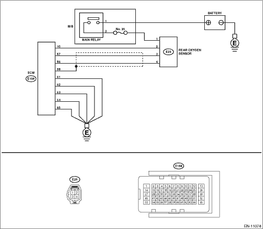
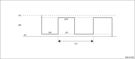
1. OUTLINE OF DIAGNOSIS

Detect the rear oxygen sensor heater open or short circuit.

The rear oxygen sensor heater performs duty control, and the output terminal voltage at ON is 0 V, and the output terminal voltage at OFF is the battery voltage.

Judge as NG when the terminal voltage remains Low.

2. COMPONENT DESCRIPTION

(A)

Battery voltage

(B)

Output voltage of the rear oxygen sensor heater

(C)

256 ms (cycles)

(D)

Low error

3. EXECUTION CONDITION

Secondary Parameters

Execution condition

Battery voltage

≥ 10.9 V

Rear oxygen sensor heater control duty

< 75 %

4. GENERAL DRIVING CYCLE

Perform the diagnosis continuously after the enable conditions have been established.

5. DIAGNOSTIC METHOD

If the duration of time while the following conditions are met is longer than the time indicated, judge as NG.

Judgment Value

Malfunction Criteria

Threshold Value

Output voltage

< Battery voltage - 0.2

Time Needed for Diagnosis: 10 seconds

Malfunction Indicator Light Illumination: Illuminates when malfunction occurs in 2 continuous driving cycles.

Dtc p0038 a/f / o2 heater control circuit high bank 1 sensor 2
DTC DETECTING CONDITION:Detected when two consecutive driving cycles with fault occur.CAUTION:After servicing or replacing faulty parts, perform Clear Memory Mode Clear Memory Mode > OPERATION, and I ...

Dtc p0032 a/f / o2 heater control circuit high bank 1 sensor 1
DTC DETECTING CONDITION:Immediately at fault recognitionCAUTION:After servicing or replacing faulty parts, perform Clear Memory Mode Clear Memory Mode > OPERATION, and Inspection Mode Inspection Mod ...

Other materials:

Adjustment
1. Disconnect the ground terminal from battery sensor. NOTE2. Release the shift lock using a screwdriver to shift the select lever to the “N” range.3. Remove the front exhaust pipe. Front Exhaust Pipe > REMOVAL4. Remove the harness stay from transmission.5. Loosen the two bolts holding ...

© 2017-2024 Copyright www.sulegacy.com