Honda Civic manuals

Subaru Legacy BN/BS (2015-2019) Service Manual: Dtc p0158 o2 sensor circuit high voltage bank 2 sensor 2

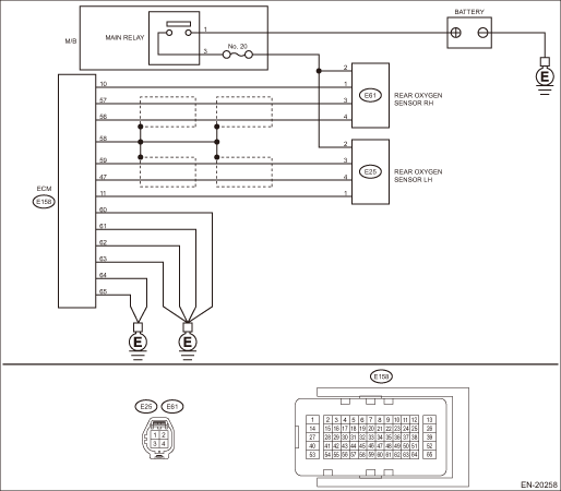
DTC DETECTING CONDITION:

Detected when two consecutive driving cycles with fault occur.

CAUTION:

After servicing or replacing faulty parts, perform Clear Memory Mode Clear Memory Mode > OPERATION, and Inspection Mode Inspection Mode > PROCEDURE.

WIRING DIAGRAM:

Engine Electrical System ENGINE TYPE EZ (WITHOUT PUSH BUTTON START) Engine Electrical System > WIRING DIAGRAM

Engine Electrical System ENGINE TYPE EZ (WITH PUSH BUTTON START) Engine Electrical System > WIRING DIAGRAM

STEPCHECKYESNO

1.CHECK REAR OXYGEN SENSOR DATA.

1) Warm up the engine until engine coolant temperature is higher than 75°C (167°F), and rapidly reduce the engine speed from 3,000 rpm.

2) Read the value of «Front O2 Sensor #2» using the Subaru Select Monitor or a general scan tool.

NOTE:

Subaru Select Monitor

For detailed operation procedures, refer to “Read Current Data For Engine”. Subaru Select Monitor

General scan tool

For detailed operation procedures, refer to the general scan tool operation manual.

Is the value of «Front O2 Sensor #2» 0.250 V or less-

Diagnostic Procedure with Diagnostic Trouble Code (DTC) > DTC P0158 O2 SENSOR CIRCUIT HIGH VOLTAGE BANK 2 SENSOR 2

Diagnostic Procedure with Diagnostic Trouble Code (DTC) > DTC P0158 O2 SENSOR CIRCUIT HIGH VOLTAGE BANK 2 SENSOR 2

2.CHECK REAR OXYGEN SENSOR CONNECTOR AND COUPLING CONNECTOR.

Has water entered the connector-

Completely remove any water inside.

Diagnostic Procedure with Diagnostic Trouble Code (DTC) > DTC P0158 O2 SENSOR CIRCUIT HIGH VOLTAGE BANK 2 SENSOR 2

3.CHECK HARNESS BETWEEN ECM AND REAR OXYGEN SENSOR CONNECTOR.

1) Turn the ignition switch to OFF.

2) Disconnect the connector from ECM and rear oxygen sensor.

3) Measure the resistance of harness between ECM connector and rear oxygen sensor connector.

Connector & terminal

(E158) No. 59 — (E25) No. 3:

(E158) No. 47 — (E25) No. 4:

Is the resistance less than 1 --

Diagnostic Procedure with Diagnostic Trouble Code (DTC) > DTC P0158 O2 SENSOR CIRCUIT HIGH VOLTAGE BANK 2 SENSOR 2

Repair the harness and connector.

NOTE:

In this case, repair the following item:

Open circuit in harness between ECM connector and rear oxygen sensor connector

Poor contact of coupling connector

4.CHECK HARNESS BETWEEN ECM AND REAR OXYGEN SENSOR CONNECTOR.

1) Connect the connector to ECM.

2) Turn the ignition switch to ON.

3) Measure the voltage between rear oxygen sensor connector and chassis ground.

Connector & terminal

(E25) No. 3 (+) — Chassis ground (−):

Is the voltage 0.2 — 0.5 V-

Replace the rear oxygen sensor. Rear Oxygen Sensor

Repair the harness and connector.

NOTE:

In this case, repair the following item:

Open circuit in harness between ECM connector and rear oxygen sensor connector

Poor contact of ECM connector

Poor contact of coupling connector

5.CHECK EXHAUST SYSTEM.

Check exhaust system parts.

NOTE:

Check the following items.

Looseness and improper fitting of exhaust system parts

Damage (crack, hole etc.) of parts

Loose part and improper installation between front oxygen (A/F) sensor and rear oxygen sensor

Is there any fault in exhaust system-

Repair or replace faulty parts.

Replace the rear oxygen sensor. Rear Oxygen Sensor

1. OUTLINE OF DIAGNOSIS

NOTE:

For the detection standard, refer to DTC P0138. Diagnostic Procedure with Diagnostic Trouble Code (DTC) > DTC P0138 O2 SENSOR CIRCUIT HIGH VOLTAGE BANK 1 SENSOR 2

Dtc p015c a/f / o2 sensor delayed response - rich to lean bank 2 sensor 1
NOTE:For the diagnostic procedure, refer to DTC P014E. Diagnostic Procedure with Diagnostic Trouble Code (DTC) > DTC P014E A/F / O2 SENSOR SLOW RESPONSE - RICH TO LEAN BANK 2 SENSOR 11. OUTLINE OF DI ...

Dtc p0157 o2 sensor circuit low voltage bank 2 sensor 2
DTC DETECTING CONDITION:Detected when two consecutive driving cycles with fault occur.CAUTION:After servicing or replacing faulty parts, perform Clear Memory Mode Clear Memory Mode > OPERATION, and I ...

Other materials:

Inspection
1. CHECK FUSE1. Remove the fuse and inspect visually.2. If the fuse is blown out, replace the fuse.2. CHECK RELAY1. Measure the resistance between relay terminals.Terminal No.Inspection conditionsStandardCircuit1 — 2Always1 M- or more1 — 2Apply battery voltage between terminals 4 and 3.Less than ...

© 2017-2024 Copyright www.sulegacy.com