Honda Civic manuals

Subaru Legacy BN/BS (2015-2019) Service Manual: Dtc p0230 fuel pump primary circuit

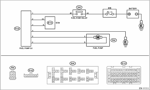
DTC DETECTING CONDITION:

Detected when two consecutive driving cycles with fault occur.

CAUTION:

After servicing or replacing faulty parts, perform Clear Memory Mode Clear Memory Mode > OPERATION, and Inspection Mode Inspection Mode > PROCEDURE.

WIRING DIAGRAM:

Engine Electrical System ENGINE TYPE EZ (WITHOUT PUSH BUTTON START) Engine Electrical System > WIRING DIAGRAM

Engine Electrical System ENGINE TYPE EZ (WITH PUSH BUTTON START) Engine Electrical System > WIRING DIAGRAM

STEPCHECKYESNO

1.CHECK POWER SUPPLY CIRCUIT TO FUEL PUMP CONTROL UNIT.

1) Turn the ignition switch to OFF.

2) Disconnect the connector from fuel pump control unit.

3) Turn the ignition switch to ON.

4) Measure the voltage between fuel pump control unit and chassis ground.

Connector & terminal

(R122) No. 1 (+) — Chassis ground (−):

Is the voltage 10 V or more-

Diagnostic Procedure with Diagnostic Trouble Code (DTC) > DTC P0230 FUEL PUMP PRIMARY CIRCUIT

Repair the power supply circuit.

NOTE:

In this case, repair the following item:

Open circuit or short circuit to ground in harness between fuel pump relay connector and fuel pump control unit connector

Poor contact of fuel pump relay connector

Poor contact of coupling connector

Blown out of fuse (M/B No. 13)

2.CHECK GROUND CIRCUIT OF FUEL PUMP CONTROL UNIT.

1) Turn the ignition switch to OFF.

2) Measure the resistance of harness between fuel pump control unit and chassis ground.

Connector & terminal

(R122) No. 4 — Chassis ground:

Is the resistance less than 5 --

Diagnostic Procedure with Diagnostic Trouble Code (DTC) > DTC P0230 FUEL PUMP PRIMARY CIRCUIT

Repair the open circuit in harness between fuel pump control unit connector and chassis ground.

3.CHECK HARNESS BETWEEN FUEL PUMP CONTROL UNIT AND FUEL PUMP CONNECTOR.

1) Disconnect the connector from fuel pump.

2) Measure the resistance of harness between fuel pump control unit and fuel pump connector.

Connector & terminal

(R122) No. 6 — (R58) No. 5:

(R122) No. 5 — (R58) No. 6:

Is the resistance less than 1 --

Diagnostic Procedure with Diagnostic Trouble Code (DTC) > DTC P0230 FUEL PUMP PRIMARY CIRCUIT

Repair the open circuit in harness between fuel pump control unit connector and fuel pump connector.

4.CHECK HARNESS BETWEEN FUEL PUMP CONTROL UNIT AND FUEL PUMP CONNECTOR.

Measure the resistance between fuel pump control unit and chassis ground.

Connector & terminal

(R122) No. 5 — Chassis ground:

(R122) No. 6 — Chassis ground:

Is the resistance 1 M- or more-

Diagnostic Procedure with Diagnostic Trouble Code (DTC) > DTC P0230 FUEL PUMP PRIMARY CIRCUIT

Repair the short circuit to ground in harness between fuel pump control unit connector and fuel pump connector.

5.CHECK HARNESS BETWEEN ECM AND FUEL PUMP CONTROL UNIT.

1) Disconnect the connector from ECM.

2) Measure the resistance of harness between ECM connector and fuel pump control unit.

Connector & terminal

(B134) No. 63 — (R122) No. 2:

(B134) No. 8 — (R122) No. 3:

Is the resistance less than 1 --

Diagnostic Procedure with Diagnostic Trouble Code (DTC) > DTC P0230 FUEL PUMP PRIMARY CIRCUIT

Repair the harness and connector.

NOTE:

In this case, repair the following item:

Open circuit in harness between ECM connector and fuel pump control unit connector

Poor contact of coupling connector

6.CHECK HARNESS BETWEEN ECM AND FUEL PUMP CONTROL UNIT.

Measure the resistance between fuel pump control unit and chassis ground.

Connector & terminal

(R122) No. 2 — Chassis ground:

(R122) No. 3 — Chassis ground:

Is the resistance 1 M- or more-

Diagnostic Procedure with Diagnostic Trouble Code (DTC) > DTC P0230 FUEL PUMP PRIMARY CIRCUIT

Repair the short circuit to ground in harness between ECM connector and fuel pump control unit connector.

7.CHECK FOR POOR CONTACT.

Check for poor contact of ECM and fuel pump control unit connector.

Is there poor contact of ECM or fuel pump control unit connector-

Repair the poor contact of ECM or fuel pump control unit connector.

Diagnostic Procedure with Diagnostic Trouble Code (DTC) > DTC P0230 FUEL PUMP PRIMARY CIRCUIT

8.CHECK EXPERIENCE OF RUNNING OUT OF FUEL.

Has the vehicle experienced running out of fuel-

Finish the diagnosis.

NOTE:

DTC may be recorded as a result of fuel pump idling while running out of fuel.

Replace the fuel pump control unit. Fuel Pump Control Unit

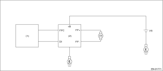
1. OUTLINE OF DIAGNOSIS

Detect the malfunction of fuel pump control unit.

Judge as NG when the NG signal is sent through a diagnostic line coming from the fuel pump control unit.

Fuel pump control unit detects the open or short circuit malfunction for each line, and then sends NG signals if one of them is found NG.

2. COMPONENT DESCRIPTION

(1)

Engine control module (ECM)

(3)

Fuel pump

(4)

Battery

(2)

Fuel pump control unit

3. EXECUTION CONDITION

Secondary Parameters

Execution condition

Battery voltage

≥ 8 V

Remaining fuel level

≥ 10.5 L (2.77 US gal, 2.31 Imp gal)

Elapsed time after starting the engine

≥ 180000 ms

4. GENERAL DRIVING CYCLE

Perform the diagnosis continuously after the enable conditions have been established.

5. DIAGNOSTIC METHOD

If the duration of time while the following conditions are met is longer than the time indicated, judge as NG.

Judgment Value

Malfunction Criteria

Threshold Value

Output voltage

≤ Battery voltage - 0.4

Time Needed for Diagnosis: 2500 ms

Malfunction Indicator Light Illumination: Illuminates when malfunction occurs in 2 continuous driving cycles.

Dtc p0300 random/multiple cylinder misfire detected
DTC DETECTING CONDITION:• Detected when two consecutive driving cycles with fault occur.• Immediately at fault recognition (A misfire which could damage catalyst occurs.)TROUBLE SYMPTOM:&b ...

Dtc p0223 throttle/pedal position sensor/switch "b" circuit high
DTC DETECTING CONDITION:Immediately at fault recognitionTROUBLE SYMPTOM:• Improper idling• Poor driving performance• Engine stalls.CAUTION:After servicing or replacing faulty parts, ...

Other materials:

Dtc p0451 evap system (cpc) pressure sensor/switch circuit range/performance
DTC DETECTING CONDITION:Detected when two consecutive driving cycles with fault occur.CAUTION:After servicing or replacing faulty parts, perform Clear Memory Mode Clear Memory Mode > OPERATION, and Inspection Mode Inspection Mode > PROCEDURE.STEPCHECKYESNO1.CHECK FOR ANY OTHER DTC ON DISPLAY.Is an ...

© 2017-2024 Copyright www.sulegacy.com