Subaru Legacy BN/BS (2015-2019) Service Manual: Dtc p0327 knock/combustion vibration sensor 1 circuit low bank 1 or single sensor
DTC DETECTING CONDITION: Immediately at fault recognition TROUBLE SYMPTOM: • Poor driving performance • Knocking occurs CAUTION: After servicing or replacing faulty parts, perform Clear Memory Mode Clear Memory Mode > OPERATION, and Inspection Mode Inspection Mode > PROCEDURE. WIRING DIAGRAM: • Engine Electrical System ENGINE TYPE EZ (WITHOUT PUSH BUTTON START) Engine Electrical System > WIRING DIAGRAM • Engine Electrical System ENGINE TYPE EZ (WITH PUSH BUTTON START) Engine Electrical System > WIRING DIAGRAM
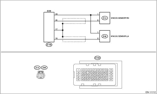
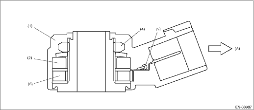
1. OUTLINE OF DIAGNOSIS Detect the open or short circuit of knock sensor. Judge as NG if out of specification. 2. COMPONENT DESCRIPTION
3. EXECUTION CONDITION
4. GENERAL DRIVING CYCLE Always perform the diagnosis continuously. 5. DIAGNOSTIC METHOD If the duration of time while the following conditions are met is longer than the time indicated, judge as NG.
Time Needed for Diagnosis: 1000 ms Malfunction Indicator Light Illumination: Illuminates as soon as a malfunction occurs. |
 Dtc p0328 knock/combustion vibration sensor 1 circuit high bank 1 or single sensor
DTC DETECTING CONDITION:Immediately at fault recognitionTROUBLE SYMPTOM:• Poor driving performance• Knocking occursCAUTION:After servicing or replacing faulty parts, perform Clear Memory M ...
 Dtc p0304 cylinder 4 misfire detected
NOTE:For the diagnostic procedure, refer to DTC P0306. Diagnostic Procedure with Diagnostic Trouble Code (DTC) > DTC P0306 CYLINDER 6 MISFIRE DETECTED1. OUTLINE OF DIAGNOSISNOTE:For the detection sta ...
Other materials:
Removal
1. Disconnect the ground terminal from battery sensor. NOTE2. Remove the overhead console. (Models without EyeSight) Spot Map Light > REMOVAL3. Remove the stereo camera cover assembly. (Models with EyeSight) Stereo Camera > REMOVAL4. Remove the motor assembly - sunroof.(1) Disconnect the harness ...
