Honda Civic manuals

Subaru Legacy BN/BS (2015-2019) Service Manual: Dtc p2747 intermediate shaft speed sensor "b" circuit no signal

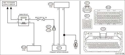
DTC DETECTING CONDITION:

Immediately at fault recognition

TROUBLE SYMPTOM:

Standing start problems

Shock occurs when engaging the lockup clutch.

Shock occurs when selecting shift position.

1. ENGINE TYPE FB

WIRING DIAGRAM:

CVT control system CVT Control System > WIRING DIAGRAM

STEPCHECKYESNO

1.CHECK FUSE.

1) Turn the ignition switch to OFF.

2) Check the M/B fuse No. 26.

Is the fuse OK-

Diagnostic Procedure with Diagnostic Trouble Code (DTC) > DTC P2747 INTERMEDIATE SHAFT SPEED SENSOR "B" CIRCUIT NO SIGNAL

Replace the fuse. If the fuse blows out easily, repair the short circuit of harness.

2.CHECK ECM CONNECTOR.

Check the connecting condition of ECM connector.

Is the ECM connector correctly connected-

Diagnostic Procedure with Diagnostic Trouble Code (DTC) > DTC P2747 INTERMEDIATE SHAFT SPEED SENSOR "B" CIRCUIT NO SIGNAL

Connect the ECM connector correctly.

3.CHECK HARNESS BETWEEN TRANSMISSION CONNECTOR AND MAIN RELAY CONNECTOR.

1) Turn the ignition switch to OFF.

2) Measure the voltage between transmission connector and engine ground.

Connector & terminal

(B11) No. 6 (+) — Engine ground (−):

Is the voltage 10 V or more-

Repair the harness and connector.

NOTE:

In this case, repair the following item:

Short circuit to power supply of harness between transmission connector and main relay connector

Defective main relay

Diagnostic Procedure with Diagnostic Trouble Code (DTC) > DTC P2747 INTERMEDIATE SHAFT SPEED SENSOR "B" CIRCUIT NO SIGNAL

4.CHECK HARNESS BETWEEN ECM AND MAIN RELAY CONNECTOR.

1) Turn the ignition switch to OFF.

2) Remove the main relay.

3) Disconnect the connector from ECM.

4) Measure the resistance between the ECM connector and engine ground.

Connector & terminal

(B134) No. 60 — Engine ground:

Is the resistance 1 M- or more-

Diagnostic Procedure with Diagnostic Trouble Code (DTC) > DTC P2747 INTERMEDIATE SHAFT SPEED SENSOR "B" CIRCUIT NO SIGNAL

Repair the short circuit to ground in harness between ECM connector and main relay connector.

5.CHECK HARNESS.

1) Turn the ignition switch to OFF.

2) Disconnect the connector of TCM and the primary speed sensor.

3) Measure the resistance between TCM connector and the primary speed sensor connector.

Connector & terminal

(T10) No. 14 — (AT1) No. 2:

(T10) No. 42 — (AT1) No. 1:

Is the resistance less than 1 --

Diagnostic Procedure with Diagnostic Trouble Code (DTC) > DTC P2747 INTERMEDIATE SHAFT SPEED SENSOR "B" CIRCUIT NO SIGNAL

Repair the open circuit of harness.

6.CHECK HARNESS.

Measure the resistance between TCM connector and chassis ground.

Connector & terminal

(T10) No. 14 — Chassis ground:

Is the resistance 1 M- or more-

Diagnostic Procedure with Diagnostic Trouble Code (DTC) > DTC P2747 INTERMEDIATE SHAFT SPEED SENSOR "B" CIRCUIT NO SIGNAL

Repair the short circuit of harness.

7.CHECK TRANSMISSION HARNESS.

1) Install the fuse.

2) Connect the TCM connector.

3) Disconnect the transmission connector.

4) Turn the ignition switch to ON.

5) Measure the voltage between transmission connector terminals.

Connector & terminal

(B11) No. 6 (+) — Chassis ground (−):

Is the voltage 10 — 13 V-

Diagnostic Procedure with Diagnostic Trouble Code (DTC) > DTC P2747 INTERMEDIATE SHAFT SPEED SENSOR "B" CIRCUIT NO SIGNAL

Repair the open circuit of harness or poor contact of connector.

8.CHECK INPUT SIGNAL FOR TCM.

1) Turn the ignition switch to OFF.

2) Connect all connectors.

3) Lift up the vehicle.

4) Start the engine.

5) Set the select lever to “D” range.

6) Read the data of «Primary Pulley Speed» using Subaru Select Monitor.

Does the value of «Primary Pulley Speed» change according to those of «Turbine Revolution Speed»-

Current condition is normal. Repair the poor contacts of harnesses of primary speed sensor and transmission connector.

Diagnostic Procedure with Diagnostic Trouble Code (DTC) > DTC P2747 INTERMEDIATE SHAFT SPEED SENSOR "B" CIRCUIT NO SIGNAL

9.CHECK TRANSMISSION HARNESS.

1) Turn the ignition switch to OFF.

2) Disconnect the transmission connector.

3) Disconnect the primary speed sensor connector.

4) Measure the resistance between transmission connector and primary speed sensor connector.

Connector & terminal

(T14) No. 6 — (AT1) No. 3:

Is the resistance less than 1 --

Diagnostic Procedure with Diagnostic Trouble Code (DTC) > DTC P2747 INTERMEDIATE SHAFT SPEED SENSOR "B" CIRCUIT NO SIGNAL

Replace the transmission harness.

10.CHECK PRIMARY SPEED SENSOR.

1) Turn the ignition switch to OFF.

2) Replace the primary speed sensor. Primary Speed Sensor

3) Perform the Clear Memory Mode. Clear Memory Mode

4) Read the DTC.

Is DTC P2747 displayed-

Diagnostic Procedure with Diagnostic Trouble Code (DTC) > DTC P2747 INTERMEDIATE SHAFT SPEED SENSOR "B" CIRCUIT NO SIGNAL

The original primary speed sensor is defective.

11.CHECK MAIN RELAY.

1) Turn the ignition switch to OFF.

2) Replace the main relay.

3) Perform the Clear Memory Mode. Clear Memory Mode

4) Read the DTC.

Is DTC P2747 displayed-

Replace the TCM. Transmission Control Module (TCM)

The original main relay is defective.

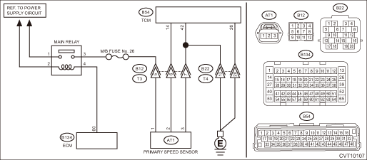
2. ENGINE TYPE EZ

WIRING DIAGRAM:

CVT control system CVT Control System > WIRING DIAGRAM

STEPCHECKYESNO

1.CHECK FUSE.

1) Turn the ignition switch to OFF.

2) Check the M/B fuse No. 26.

Is the fuse OK-

Diagnostic Procedure with Diagnostic Trouble Code (DTC) > DTC P2747 INTERMEDIATE SHAFT SPEED SENSOR "B" CIRCUIT NO SIGNAL

Replace the fuse. If the fuse blows out easily, repair the short circuit of harness.

2.CHECK ECM CONNECTOR.

Check the connecting condition of ECM connector.

Is the ECM connector correctly connected-

Diagnostic Procedure with Diagnostic Trouble Code (DTC) > DTC P2747 INTERMEDIATE SHAFT SPEED SENSOR "B" CIRCUIT NO SIGNAL

Connect the ECM connector correctly.

3.CHECK HARNESS BETWEEN TRANSMISSION CONNECTOR AND MAIN RELAY CONNECTOR.

1) Turn the ignition switch to OFF.

2) Measure the voltage between transmission connector and engine ground.

Connector & terminal

(B12) No. 5 (+) — Engine ground (−):

Is the voltage 10 V or more-

Repair the harness and connector.

NOTE:

In this case, repair the following item:

Short circuit to power supply of harness between transmission connector and main relay connector

Defective main relay

Diagnostic Procedure with Diagnostic Trouble Code (DTC) > DTC P2747 INTERMEDIATE SHAFT SPEED SENSOR "B" CIRCUIT NO SIGNAL

4.CHECK HARNESS BETWEEN ECM AND MAIN RELAY CONNECTOR.

1) Turn the ignition switch to OFF.

2) Remove the main relay.

3) Disconnect the connector from ECM.

4) Measure the resistance between the ECM connector and engine ground.

Connector & terminal

(B134) No. 60 — Engine ground:

Is the resistance 1 M- or more-

Diagnostic Procedure with Diagnostic Trouble Code (DTC) > DTC P2747 INTERMEDIATE SHAFT SPEED SENSOR "B" CIRCUIT NO SIGNAL

Repair the short circuit to ground in harness between ECM connector and main relay connector.

5.CHECK HARNESS.

1) Turn the ignition switch to OFF.

2) Disconnect the TCM and transmission connectors.

3) Measure the resistance between TCM connector and transmission connectors.

Connector & terminal

(B54) No. 26 — (B22) No. 20:

(B54) No. 42 — (B22) No. 13:

(B54) No. 14 — (B12) No. 6:

(B54) No. 42 — (B12) No. 7:

Is the resistance less than 1 --

Diagnostic Procedure with Diagnostic Trouble Code (DTC) > DTC P2747 INTERMEDIATE SHAFT SPEED SENSOR "B" CIRCUIT NO SIGNAL

Repair the open circuit of harness.

6.CHECK HARNESS.

Measure the resistance between TCM connector and chassis ground.

Connector & terminal

(B54) No. 14 — Chassis ground:

Is the resistance 1 M- or more-

Diagnostic Procedure with Diagnostic Trouble Code (DTC) > DTC P2747 INTERMEDIATE SHAFT SPEED SENSOR "B" CIRCUIT NO SIGNAL

Repair the short circuit of harness.

7.CHECK TRANSMISSION HARNESS.

1) Install the fuse.

2) Connect the TCM connector.

3) Turn the ignition switch to ON.

4) Measure the voltage between transmission connector terminals.

Connector & terminal

(B12) No. 5 (+) — Chassis ground (−):

Is the voltage 10 — 13 V-

Diagnostic Procedure with Diagnostic Trouble Code (DTC) > DTC P2747 INTERMEDIATE SHAFT SPEED SENSOR "B" CIRCUIT NO SIGNAL

Repair the open circuit of harness or poor contact of connector.

8.CHECK INPUT SIGNAL FOR TCM.

1) Turn the ignition switch to OFF.

2) Connect the transmission connector.

3) Lift up the vehicle.

4) Start the engine.

5) Set the select lever to “D” range.

6) Read the data of «Primary Pulley Speed» using Subaru Select Monitor.

Does the value of «Primary Pulley Speed» change according to those of «Turbine Revolution Speed»-

Current condition is normal. Repair the poor contacts of harnesses of primary speed sensor and transmission connector.

Diagnostic Procedure with Diagnostic Trouble Code (DTC) > DTC P2747 INTERMEDIATE SHAFT SPEED SENSOR "B" CIRCUIT NO SIGNAL

9.CHECK TRANSMISSION HARNESS.

1) Turn the ignition switch to OFF.

2) Disconnect the transmission connector.

3) Disconnect the primary speed sensor connector.

4) Measure the resistance between transmission connector and primary speed sensor connector.

Connector & terminal

(T3) No. 5 — (AT1) No. 1:

(T3) No. 6 — (AT1) No. 2:

(T3) No. 7 — (AT1) No. 3:

Is the resistance less than 1 --

Diagnostic Procedure with Diagnostic Trouble Code (DTC) > DTC P2747 INTERMEDIATE SHAFT SPEED SENSOR "B" CIRCUIT NO SIGNAL

Replace the transmission harness.

10.CHECK PRIMARY SPEED SENSOR.

1) Turn the ignition switch to OFF.

2) Replace the primary speed sensor. Primary Speed Sensor

3) Perform the Clear Memory Mode. Clear Memory Mode

4) Read the DTC.

Is DTC P2747 displayed-

Diagnostic Procedure with Diagnostic Trouble Code (DTC) > DTC P2747 INTERMEDIATE SHAFT SPEED SENSOR "B" CIRCUIT NO SIGNAL

The original primary speed sensor is defective.

11.CHECK MAIN RELAY.

1) Turn the ignition switch to OFF.

2) Replace the main relay.

3) Perform the Clear Memory Mode. Clear Memory Mode

4) Read the DTC.

Is DTC P2747 displayed-

Replace the TCM. Transmission Control Module (TCM)

The original main relay is defective.

3. OUTLINE OF DIAGNOSIS (ENGINE TYPE FB)

Detect no input signal from the primary speed sensor.

Judge as NG if there is no input signal from the primary pulley speed sensor, while the secondary pulley speed sensor has the input signal although the primary and secondary pulleys are interlocked via the chain.

4. EXECUTION CONDITION (ENGINE TYPE FB)

Secondary Parameters

Execution condition

12 V battery system voltage

≥ 9 V

Measured secondary pulley shaft speed

≥ 500 rpm

5. DIAGNOSTIC METHOD (ENGINE TYPE FB)

If the duration of time while the following conditions are met is longer than the time indicated, judge as NG.

Judgment Value

Malfunction Criteria

Threshold Value

Measured primary pulley shaft speed

0 rpm

Time Needed for Diagnosis: 0.5 seconds

Malfunction Indicator Light Illumination: Illuminates as soon as a malfunction occurs.

6. OUTLINE OF DIAGNOSIS (ENGINE TYPE EZ)

Detect no input signal from the primary speed sensor.

Judge as NG if there is no input signal from the primary pulley speed sensor, while the secondary pulley speed sensor has the input signal although the primary and secondary pulleys are interlocked via the chain.

7. EXECUTION CONDITION (ENGINE TYPE EZ)

Secondary Parameters

Execution condition

12 V battery system voltage

≥ 10 V

Measured secondary pulley shaft speed

≥ 500 rpm

8. DIAGNOSTIC METHOD (ENGINE TYPE EZ)

If the duration of time while the following conditions are met is longer than the time indicated, judge as NG.

Judgment Value

Malfunction Criteria

Threshold Value

Measured primary pulley shaft speed

0 rpm

Time Needed for Diagnosis: 0.5 seconds

Malfunction Indicator Light Illumination: Illuminates as soon as a malfunction occurs.

Dtc p2750 intermediate shaft speed sensor "c" circuit range/performance
DTC DETECTING CONDITION:Immediately at fault recognitionTROUBLE SYMPTOM:• Shifting shock is felt.• Acceleration is poor during standing start.• Shift control malfunction1. ENGINE TYP ...

Dtc p2746 intermediate shaft speed sensor "b" circuit range/performance
DTC DETECTING CONDITION:Immediately at fault recognitionTROUBLE SYMPTOM:• Standing start problems• Shock occurs when engaging the lockup clutch.• Shock occurs when selecting shift po ...

Other materials:

Installation
1. Install the auto headlight beam leveler CM.Tightening torque:7.5 N·m (0.8 kgf-m, 5.5 ft-lb)2. Install the relay holder.3. Install the panel - knee guard.Tightening torque:7 N·m (0.7 kgf-m, 5.2 ft-lb)4. Install the cover assembly - instrument panel LWR driver.5. Connect the ground te ...

© 2017-2024 Copyright www.sulegacy.com