Honda Civic manuals

Subaru Legacy BN/BS (2015-2019) Service Manual: Electrical specification

Item

Connector No.

Terminal No.

Input/Output signal

Measured value and measuring conditions

Battery power supply

B280

4

9 — 16 V

7

B281

32

TCM (“P” range)

i171

2

Pulse signal (CAN communication)

22

Stop light switch

B281

12

9 — 16 V when stop light switch is ON.

Less than 1.5 V when stop light switch is OFF.

“P” range switch

i171

25

Less than 1.5 V when select lever is in “P” range.

9 — 16 V when select lever is in other positions than “P” range.

Solenoid unit output

i84

3

8.5 — 16 V when shift lock is released.

Less than 1.5 V when shift lock is operating.

Key warning switch signal

(Model without push button ignition switch)

i84

10

9 — 16 V when key is inserted.

Less than 1.5 V when key is removed.

Key lock solenoid signal

(Model without push button ignition switch)

B280

5

7.5 — 16 V when the key is inserted with the select lever shifted in positions other than “P” range.

0 V at other conditions than above.

Ground

i84

4

1 V or less

B280

2

Wiring diagram
1. MODEL WITHOUT PUSH BUTTON IGNITION SWITCH(1)Ignition switch(5)Key warning switch(9)TCM (shift range information)(2)Accessory 1 relay(6)Battery(10)Key lock solenoid(3)IG2 relay(7)Body integrated uni ...
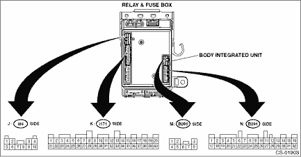
Location
1. MODEL WITHOUT PUSH BUTTON IGNITION SWITCH(1)TCM (engine type: EZ)(4)Stop light switch(7)“P” range switch(2)TCM (engine type: FB)(5)Key cylinder (with built-in key warning switch)(8)Key ...

Other materials:

Check power supply and ground line of engine control module (ecm)
CAUTION:After servicing or replacing faulty parts, perform Clear Memory Mode Clear Memory Mode > OPERATION, and Inspection Mode Inspection Mode > PROCEDURE.WIRING DIAGRAM:• Engine Electrical System ENGINE TYPE EZ (WITHOUT PUSH BUTTON START) Engine Electrical System > WIRING DIAGRAM• E ...

© 2017-2024 Copyright www.sulegacy.com