Subaru Legacy BN/BS (2015-2019) Service Manual: Electrical specification
1. STEREO CAMERA
2. ENGINE CONTROL MODULE (ECM) For details on the input/output signals for the engine control module, refer to ENGINE (DIAGNOSTICS). Engine Control Module (ECM) I/O Signal Engine Control Module (ECM) I/O Signal 3. VDC CONTROL MODULE (VDCCM) For details on the input/output signals for VDC control module, refer to VDC (DIAGNOSTICS). Control Module I/O Signal > ELECTRICAL SPECIFICATION 4. TRANSMISSION CONTROL MODULE (TCM) For details on the input/output signals for the transmission control module, refer to AUTOMATIC TRANSMISSION (DIAGNOSTICS). Transmission Control Module (TCM) I/O Signal 5. BODY INTEGRATED UNIT Refer to the BODY CONTROL SYSTEM (DIAGNOSTICS) for the I/O Signal of the body integrated unit. Control Module I/O Signal > ELECTRICAL SPECIFICATION 6. COMBINATION METER For details on the input/output signals for the combination meter, refer to COMBINATION METER (DIAGNOSTICS). Control Module I/O Signal > ELECTRICAL SPECIFICATION |
 System block diagram
Main signals used between stereo camera and relevant CM ...
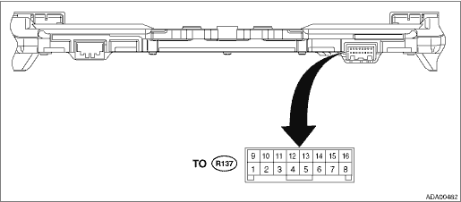
 Wiring diagram
Refer to “EyeSight System” in the wiring diagram. EyeSight System ...
Other materials:
Installation
NOTE:Make sure that there are no differences from the contents of the current settings after installation. Read Current Data > LIST1. Install the reinforcement - combination meter and keyless access CM.NOTE:For model with navigation, install the GPS antenna assembly. GPS Antenna > INSTALLATIONTigh ...
