Subaru Legacy BN/BS (2015-2019) Service Manual: Inspection
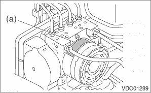
1. Check the identification (a) of the VDC control module & hydraulic control unit (VDCCM&H/U). NOTE: For the identification, refer to “SPECIFICATION” in “General Description”. General Description > SPECIFICATION
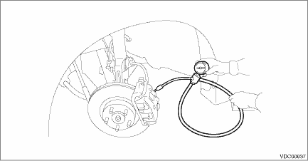
2. Check the condition of connection and settlement of connector, and correct or replace if defective. 1. CHECKING THE HYDRAULIC UNIT ABS OPERATION BY PRESSURE GAUGE 1. Lift up the vehicle, and then remove the wheel. 2. Remove the bleeder - screws from the front LH and front RH caliper bodies. 3. Connect two pressure gauges to front LH and front RH caliper bodies. CAUTION: • Use a pressure gauge used exclusively for brake fluid measurement. • Do not use the pressure gauge used for the measurement of transmission oil. Doing so will cause the piston seal to expand and deform. NOTE: Wrap sealing tape around the pressure gauge.
4. Bleed air from the pressure gauges and the front LH and front RH caliper bodies. 5. Perform ABS sequence control. ABS Sequence Control NOTE: When the hydraulic unit begins to work, first the front LH side performs decompression, hold and compression, and then the front RH side performs decompression, hold and compression. 6. Read values indicated on the pressure gauge and check if the fluctuation of the values between decompression and compression meets the standard values. Depress the brake pedal and check that the kick-back is normal, and tightness is normal.
7. Remove the pressure gauge from the front LH and front RH caliper bodies. 8. Install the bleeder - screws of the front LH and front RH caliper bodies. 9. Remove the bleeder - screws from the rear LH and rear RH caliper bodies. 10. Connect two pressure gauges to rear LH and rear RH caliper bodies. 11. Bleed air from the pressure gauges and the rear LH and rear RH caliper bodies. 12. Perform ABS sequence control. ABS Sequence Control NOTE: When the hydraulic unit begins to work, first the rear LH side performs decompression, hold and compression, and then the rear RH side performs decompression, hold and compression. 13. Read values indicated on the pressure gauge and check if the fluctuation of the values between decompression and compression meets specification. Depress the brake pedal and check that the kick-back is normal, and tightness is normal. 14. Remove the pressure gauge from the rear LH and rear RH caliper bodies. 15. Install the bleeder - screws of the rear LH and rear RH caliper bodies. 16. Bleed air from the brake system. Air Bleeding 2. CHECKING THE HYDRAULIC UNIT ABS OPERATION WITH THE BRAKE TESTER 1. Set wheels other than the one to measure on free rollers. 2. Prepare for the ABS sequence control operation. ABS Sequence Control 3. Set the front wheels or rear wheels on the brake tester and set the gear to neutral. 4. Operate the brake tester. NOTE: When any wheel speed reaches 10 km/h (6.2 MPH), the ABS sequence control stops and ABS operation is returned to the normal control mode. 5. Perform ABS sequence control. ABS Sequence Control 6. When the hydraulic unit begins to work, check the following work sequence. (1) The front LH wheel performs decompression, hold and compression in sequence, and subsequently the front RH wheel repeats the same cycle. (2) The rear RH wheel performs decompression, hold and compression in sequence, and subsequently the rear LH wheel repeats the same cycle. 7. Read values indicated on the brake tester and check if the fluctuation of the values between decompression and compression meets specification.
8. After the inspection, depress the brake pedal and check that it is not abnormally hard, and tightness is normal. 3. CHECKING THE HYDRAULIC UNIT VDC OPERATION USING A PRESSURE GAUGE 1. Lift up the vehicle, and then remove the wheel. 2. Remove the bleeder - screws from the front LH and front RH caliper bodies. 3. Connect two pressure gauges to front LH and front RH caliper bodies. CAUTION: • Use a pressure gauge used exclusively for brake fluid measurement. • Do not use a pressure gauge used for the measuring transmission oil pressure, as the piston seal may expand and deform. NOTE: Wrap sealing tape around the pressure gauge.
4. Bleed air from the pressure gauge. 5. Perform VDC sequence control. VDC Sequence Control NOTE: When the hydraulic unit begins to work, first the front LH side performs compression, hold and decompression, and then the front RH side performs compression, hold and decompression. 6. Read values indicated on the pressure gauge and check if the fluctuation of the values between decompression and compression meets specification. Depress the brake pedal and check that it is not abnormally hard, and tightness is normal.
7. Remove the pressure gauge from the front LH and front RH caliper bodies. 8. Install the bleeder - screws of the front LH and front RH caliper bodies. 9. Remove the bleeder - screws from the rear LH and rear RH caliper bodies. 10. Connect two pressure gauges to rear LH and rear RH caliper bodies. 11. Bleed air from the pressure gauges and the rear LH and rear RH caliper bodies. 12. Perform VDC sequence control. VDC Sequence Control NOTE: When the hydraulic unit begins to work, first the rear RH side performs compression, hold and decompression, and then the rear LH side performs compression, hold and decompression. 13. Read the values indicated on the pressure gauges and check if it is within specification. Depress the brake pedal and check that it is not abnormally hard, and tightness is normal. 14. Remove the pressure gauge from the rear LH and rear RH caliper bodies. 15. Install the bleeder - screws of the rear LH and rear RH caliper bodies. 16. Bleed air from the brake system. Air Bleeding 4. CHECK HYDRAULIC UNIT VDC OPERATION WITH BRAKE TESTER 1. Set wheels other than the one to measure on free rollers. 2. Prepare to operate the VDC sequence control. VDC Sequence Control 3. Set the front wheels or rear wheels on the brake tester and set the gear to neutral. 4. Operate the brake tester. NOTE: When any wheel speed reaches 10 km/h (6.2 MPH), the VDC sequence control stops and VDC operation is returned to the normal control mode. 5. Perform VDC sequence control. VDC Sequence Control 6. When the hydraulic unit begins to work, check the following work sequence. (1) The front LH wheel performs compression, hold and decompression in sequence, and subsequently the front RH wheel repeats the same cycle. (2) The rear RH wheel performs compression, hold and decompression in sequence, and subsequently the rear LH wheel repeats the same cycle. 7. Read values indicated on the brake tester and check if the fluctuation of the values between decompression and compression meets specification.
8. After the inspection, depress the brake pedal and check that it is not abnormally hard, and tightness is normal. |
 Installation
CAUTION:• When installing the VDCCM&H/U to the bracket - hydraulic unit, make sure that there is no oil adhered to the bolts and the threads of VDCCM&H/U. If the oil is adhered, degrease it care ...
 Vdc off switch
...
Other materials:
Removal
CAUTION:• Directly after the vehicle has been running or the engine has been idling for a long time, the CVTF is hot. Be careful not to burn yourself.• Be careful not to spill CVTF on the exhaust pipe to prevent it from emitting smoke or causing a fire. If the CVTF adheres, wipe it off c ...
