Subaru Legacy BN/BS (2015-2019) Service Manual: Inspection
1. SYSTEM INSPECTION
NOTE: Rear window defogger system can be customized using the Subaru Select Monitor, when the customize setting {Auto A/C Setting} of the body integrated unit is set to {support}.
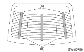
* When the battery voltage remains at 10 V or less for 30 seconds, the continuous operation is suspended and turned to the normal operation. 2. CHECK WITH SUBARU SELECT MONITOR CAUTION: Check whether the Rr Defogger op. mode setting is in initial setting or customize setting before performing inspection. 1. Check the input signal when the rear window defogger switch is operated using Subaru Select Monitor. (1) Connect the Subaru Select Monitor to data link connector. NOTE: For detailed operation procedures, refer to “Application help”. (2) Turn the ignition switch to ON. (3) On «Start» display, select «Diagnosis». (4) On «Vehicle selection» display, input the target vehicle information and select «Confirmed». (5) On «Main Menu» display, select «Each System». (6) On «Select System» display, select «Integ. Unit Mode» and select «Enter». (7) On «Select Function» display, select «Data Monitor». (8) From the data monitor item list, select «Auto A/C Setting». (9) Check the vehicle equipment and the settings of body integrated unit. If correct, go to (10). If not correct, go to (13). (10) From the data monitor item list, select «Rr Defogger output». (11) Check the displayed data (ON/OFF) by operating the rear window defogger switch. (12) On «Select Function» display, select «Customize». (13) From the Customize item list, select «Auto A/C Setting» and match the auto A/C ECM setting to the actual vehicle equipment. 2. Check the operation with rear window defogger switch ON. • When customize setting is set as “Continuous”, it is normal if the 15-minute operation and 2-minute stop repeats. • When customize setting is “Normal”, it is normal if the operation lasts for 15 minutes and then turns OFF. 3. When the operation in 2) above fails, replace the body integrated unit. 3. HEAT WIRE INSPECTION CAUTION: Use a dry soft cloth to wipe off dirt on the glass along the heat wires with care not to damage the heat wires. 1. Prepare the following checking items. • Liquid crystal thermograph sheet (approximate Size: 300 - 300 mm (11.8 - 11.8 in) and thermal temperature: 35 — 40°C (95 — 104°F)) • Aluminum foil 2. Turn the ignition switch to ON. 3. Turn the defogger switch to ON. 4. Push the liquid crystal thermograph sheet from the outside of the glass. NOTE: Use the liquid crystal thermograph sheet every range it is separated with the separate line.
5. Determine the faulty heat wire by checking the color of the liquid crystal thermograph sheet.
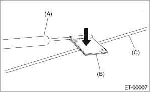
NOTE: • Check from the inside of the glass - rear window if the liquid crystal thermograph sheet does not change. • The time for the color change may differ depends on the surface temperature of the glass. 6. Wrap a piece of aluminum foil around the tip of tester probe and press it against the heat wire with your finger.
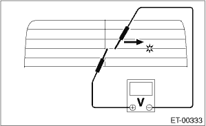
7. To both ends of the section that has been found to include an open in the step 5), apply the tester positive (+) probe and the negative (−) probe. 8. Move the tester probe on the negative (−) side slowly along the heat wire. If voltage changes from zero while moving the tester probe, heat wire is open at the voltage change point.
9. Repair the heat wire that determines the place of the open circuit. Rear Window Defogger System > REPAIR |
 Wiring diagram
Refer to “Rear Defogger System” in the wiring diagram. Rear Defogger System > WIRING DIAGRAM ...
 Repair
1. Clean the broken portion with alcohol or appropriate cleaning solvent.2. Mask both side of wire with masking tape.3. Apply the conductive silver composition to the broken portion.Conductive silver ...
Other materials:
System block diagram
• BSD/RCTA system is configured by the following components.• There is a control ECM in the radar sensor main body, which performs the vehicle identification and the alert judgment control.• The LH/RH radar sensors are identified as Master/Slave for control purposes. They are conne ...
