Subaru Legacy BN/BS (2015-2019) Service Manual: Installation
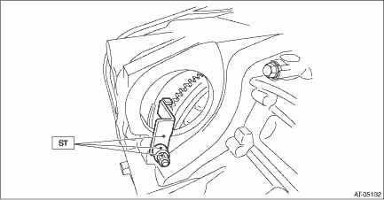
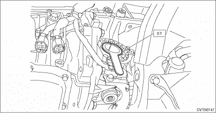
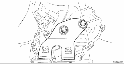
1. Attach the ST to converter case.
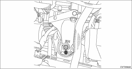
2. When completely overhauling the transmission, refill approx. 10 L (2.6 US qt, 8.8 Imp qt) of CVTF through the transmission right side plug, and install the plug. CAUTION: Always use specified CVTF. Using other fluid will cause malfunction. General Description > SPECIFICATION NOTE: Use a new gasket. Tightening torque: 35 N·m (3.6 kgf-m, 25.8 ft-lb)
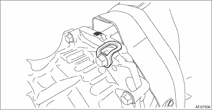
3. Replace the front differential side retainer oil seal. Differential Side Retainer Oil Seal > REPLACEMENT NOTE: • Be sure to replace the differential side retainer oil seal with a new part whenever the front drive shaft is removed from the transmission. • When a new differential side retainer oil seal has been installed, replacement is not required. 4. Install the cushion rubber on the transmission. Tightening torque: 40 N·m (4.1 kgf-m, 29.5 ft-lb)
5. Mount the transmission onto the transmission jack. 6. Strike and bend the transmission hanger of transmission rear with a soft rubber hammer etc. so that it gets in contact with the transmission case. CAUTION: Do not apply extra overload or impact to the transmission case.
7. While lifting up the transmission gradually, install the transmission to the engine. CAUTION: This operation requires at least two persons. NOTE: Keep the engine level. 8. Install the two engine connecting bolts and two nuts (lower side). Tightening torque: 50 N·m (5.1 kgf-m, 36.9 ft-lb)
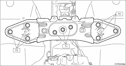
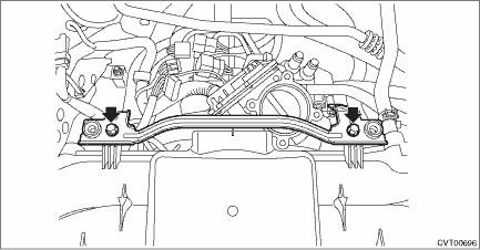
9. Secure the transmission rear crossmember to the vehicle body. Tightening torque: T1: 35 N·m (3.6 kgf-m, 25.8 ft-lb) T2: 75 N·m (7.6 kgf-m, 55.3 ft-lb)
10. Remove the transmission jack. 11. Lower the vehicle. 12. Remove the ST (ENGINE HANGER). 13. Install the three engine mounting bolts (upper side). Tightening torque: 50 N·m (5.1 kgf-m, 36.9 ft-lb)
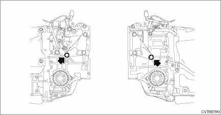
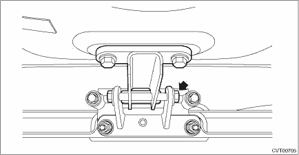
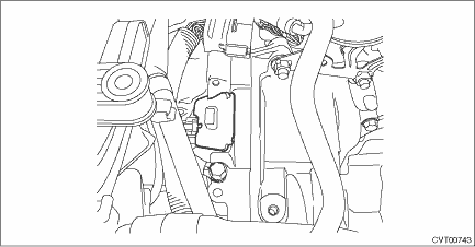
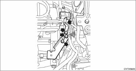
14. Install the left and right transmission mounting brackets. NOTE: • Install to the left side of vehicle first because the engine inclines to the left. • Temporarily tighten the bolt arrowed in the figure. Tightening torque: 75 N·m (7.6 kgf-m, 55.3 ft-lb)
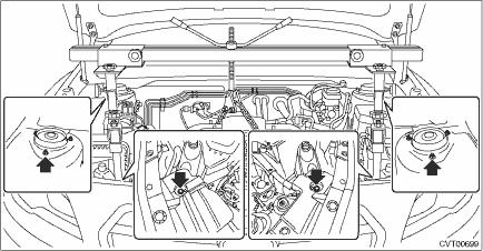
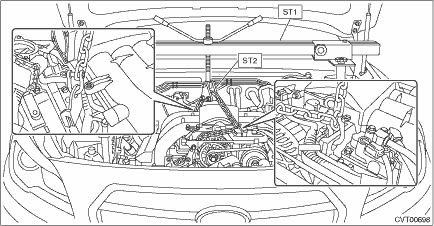
15. Set the ST1 and ST2 to the vehicle body and lift up the engine unit slightly.
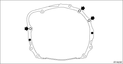
CAUTION: • Set so that the chain sling does not contact the engine parts. • Install a bolt of φ8 mm (0.3 in) at the locations shown in the figure, and place the front side arms of ST (ENGINE HANGER). • Set the rear arms of ST (ENGINE HANGER) at the locations shown in the figure.
16. Remove the bolts from ST (SPECIAL TOOL H6).
17. Remove the bolt and nut to remove ST (SPECIAL TOOL H6).
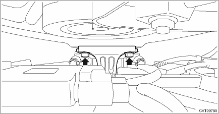
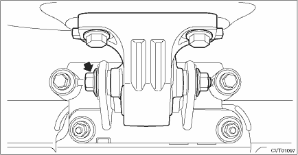
18. Temporarily attach the front cushion rubber with bolts.
19. Lift down the engine slightly and install the bolt and nut to the front cushion rubber.
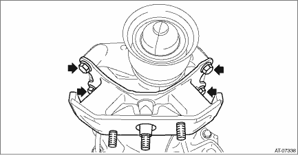
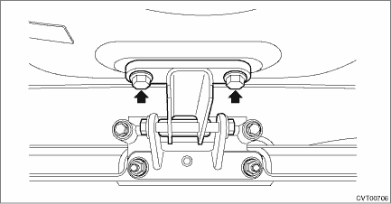
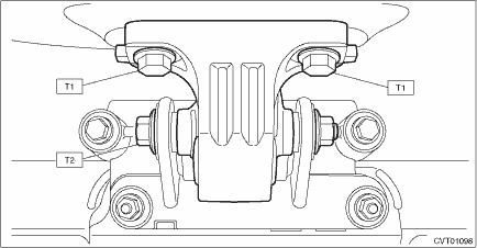
20. Tighten the bolts and nuts of front cushion rubber. NOTE: Always start tightening from the bolts on the engine side. Tightening torque: T1: 25 N·m (2.5 kgf-m, 18.4 ft-lb) T2: 45 N·m (4.6 kgf-m, 33.2 ft-lb)
21. Remove the ST (ENGINE HANGER and CHAIN SLING). CAUTION: Be sure to remove the φ8 mm (0.3 in) bolt. 22. Install the nut to the transmission mounting bracket. Tightening torque: 45 N·m (4.6 kgf-m, 33.2 ft-lb)
23. Remove the ST (STOPPER SET) from converter case. 24. Match the torque converter screw hole with drive plate hole to install the bolt. CAUTION: • Do not drop the mounting bolt in the converter housing. • Do not damage the mounting bolt. Tightening torque: 25 N·m (2.5 kgf-m, 18.4 ft-lb) 25. Install the remaining three bolts by rotating the crank pulley a little at a time in the same direction as engine revolution. Tightening torque: 25 N·m (2.5 kgf-m, 18.4 ft-lb) 26. Install the service hole plug.
27. Install the starter. Starter > INSTALLATION 28. Lift up the vehicle. 29. Tighten the single mounting bolt of transmission mounting bracket. Tightening torque: 75 N·m (7.6 kgf-m, 55.3 ft-lb)
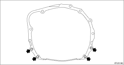
30. Set the ST to side retainer.
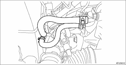
31. Replace the circlip of the drive shaft with a new part. 32. Insert the front drive shaft spline section into transmission and remove the ST (OIL SEAL PROTECTOR). 33. Insert the drive shaft into the transmission securely by pressing the housing from outside of the vehicle. 34. Install the CVTF CVT inlet hose and CVTF CVT outlet hose. NOTE: Use new CVTF CVT inlet hose and CVTF CVT outlet hose.
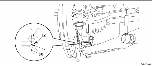
35. Insert the ball joint into housing and secure with bolt. CAUTION: • Before tightening, make sure the bottom surface of the housing assembly - front axle and the stepped section of ball joint are in contact. • Be careful not to damage the boot of the joint. Tightening torque: 50 N·m (5.1 kgf-m, 36.9 ft-lb)
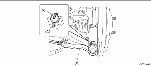
36. Install the stabilizer link. Tightening torque: 60 N·m (6.1 kgf-m, 44.3 ft-lb) 37. Connect the tie-rod end and knuckle arm, and attach the castle nut. Tightening torque: 27 N·m (2.75 kgf-m, 19.9 ft-lb) CAUTION: When connecting, do not hit the cap at the bottom of tie-rod end with hammer. 38. After tightening the castle nut to the specified tightening torque, tighten it further within 60° until the cotter pin hole is aligned with slot in the nut. Fit the cotter pin into the nut, and then bend the pin to lock.
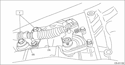
39. Install the propeller shaft. Propeller Shaft > INSTALLATION 40. Install the universal joint. Universal Joint > INSTALLATION 41. Install the plate assembly to transmission. Tightening torque: T: 25 N·m (2.5 kgf-m, 18.4 ft-lb)
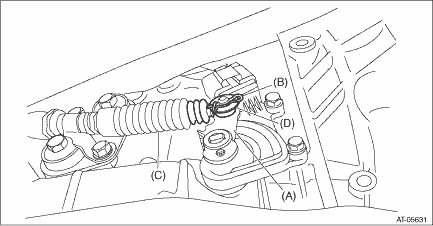
42. Install the washer and snap pin to the shifter arm.
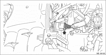
43. Install the exhaust hanger bracket. Tightening torque: 30 N·m (3.1 kgf-m, 22.1 ft-lb)
44. Install the center exhaust cover. Tightening torque: 18 N·m (1.8 kgf-m, 13.3 ft-lb)
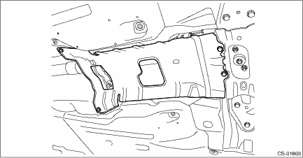
45. Install the front exhaust pipe. Front Exhaust Pipe > INSTALLATION 46. Install the front under cover. Front Under Cover > INSTALLATION 47. Lower the vehicle. 48. Remove the ST (HANGER) and install the engine rear hanger. Tightening torque: 19 N·m (1.9 kgf-m, 14.0 ft-lb)
49. Install the collector cover bracket. Tightening torque: 6.5 N·m (0.7 kgf-m, 4.8 ft-lb)
50. Connect the oxygen sensor harness connector.
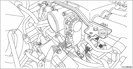
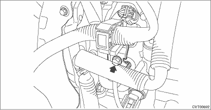
51. Install the throttle body. Throttle Body > INSTALLATION 52. Connect the engine harness connector.
53. Install the harness stay. Tightening torque: 16 N·m (1.6 kgf-m, 11.8 ft-lb)
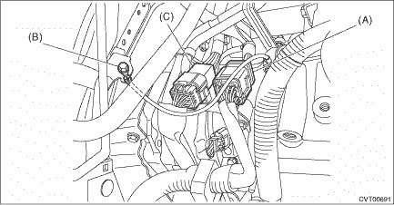
54. Connect the following harness connectors. • Transmission harness connectors • Transmission radio ground terminal • Inhibitor harness connector Tightening torque: 13 N·m (1.3 kgf-m, 9.6 ft-lb)
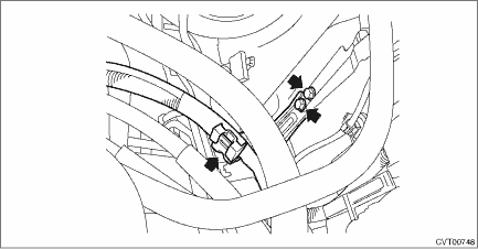
55. Install the battery cable bracket, and install the battery cable clip to the bracket. Tightening torque: 7.5 N·m (0.8 kgf-m, 5.5 ft-lb)
56. Install the air intake boot. Air Intake Boot > INSTALLATION 57. Install the air intake duct. Air Intake Duct > INSTALLATION 58. Install the front tires. 59. Connect the ground terminal to battery sensor. NOTE 60. Refill differential gear oil to adjust the differential gear oil amount. Differential Gear Oil 61. Refill CVTF to adjust the CVTF amount. CVTF 62. Perform the variator chain break-in. Variator Chain Break-in CAUTION: Always execute the variator chain break-in after the replacement of the following. • Variator chain replacement • Primary pulley and secondary pulley replacement 63. Perform the clear operation for AT learning. Clear Memory Mode 64. Perform AT learning mode. Learning Control 65. Execute the rear differential inspection mode. Rear Differential Inspection Mode CAUTION: Always execute the rear differential inspection mode after the replacement of the following. • Replacement of transmission assembly • Replacement of front differential hypoid gear set 66. Perform the road test to make sure there is no fault. Road Test > INSPECTION |

 Removal
1. Remove the front tires.2. Remove the collector cover.(1) Carefully pull up the rear of collector cover at two positions (A).(2) Carefully pull up the front of collector cover at two positions (B) w ...

Other materials:
Dtc u0230 lost communication with power rear gate control module
DTC DETECTING CONDITION:No data is received from the power rear gate CM.TROUBLE SYMPTOM:The power rear gate does not operate normally.WIRING DIAGRAM:NOTE:For the coupling connector, refer to “WIRING SYSTEM”.Power rear gate system Power Rear Gate System > WIRING DIAGRAMSTEPCHECKYESNO1.CH ...
