Subaru Legacy BN/BS (2015-2019) Service Manual: Installation
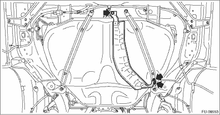
1. Support the fuel tank with a transmission jack, set the fuel tank and the fuel tank band in place, and temporarily tighten the bolts of the fuel tank band. WARNING: A helper is required to perform this work.
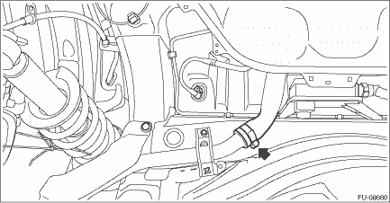
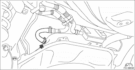
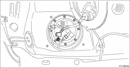
2. Correctly insert the fuel filler hose to the spool, and then install the clamp as shown. Tightening torque: 2.5 N·m (0.3 kgf-m, 1.8 ft-lb)
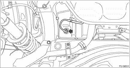
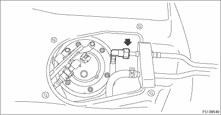
3. Connect the quick connector of the circulate tube to the evaporation pipe as shown in the figure. CAUTION: • Check that there is no damage or dust on the quick connector. If necessary, clean the seal surface of the pipe. • Make sure that the quick connector is securely connected.
4. Connect the air vent hose to fuel tank.
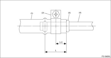
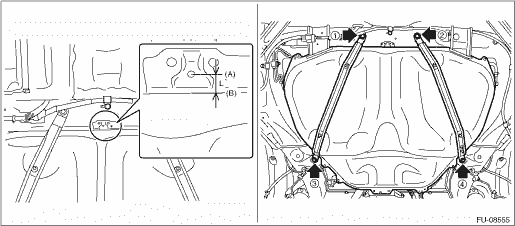
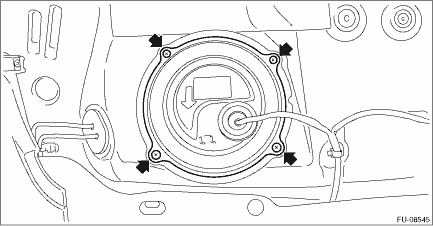
5. Move the fuel tank so that the distance between the center of the positioning hole for the body (A) and the front end of the fuel tank flange (B) becomes L, and tighten the bolts of the fuel tank bands in the sequence shown in the figure. CAUTION: To prevent the fuel tank from damage, after tightening the bolts of the fuel tank bands, make sure that the distance between the center of the positioning hole for the body (A) and the front end of the fuel tank flange (B) is L. Distance L: Center of the positioning hole for the body (A) — Front end of the fuel tank flange (B) 14.5 mm (0.571 in) or less Tightening torque: 33 N·m (3.4 kgf-m, 24.3 ft-lb)
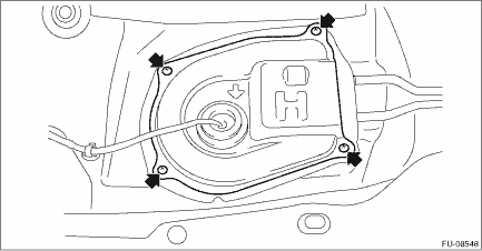
6. Install the heat shield cover. Tightening torque: 18 N·m (1.8 kgf-m, 13.3 ft-lb)
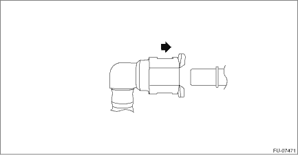
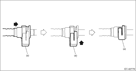
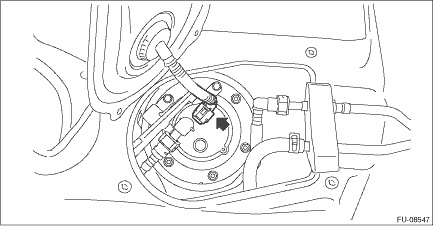
7. Install the rear sub frame assembly. Rear Sub Frame > INSTALLATION 8. Connect the quick connector of the fuel delivery tube. CAUTION: • Check that there is no damage or dust on the quick connector. If necessary, clean the seal surface of the pipe. • When connecting the quick connector, make sure to insert it all the way in before locking the slider. • When it is difficult to lock the slider, check that the connector is fully inserted. • After locking the slider, check again that the quick connector is securely connected. NOTE: Connect the quick connector as shown in the figure.
9. Connect the connector to the fuel sub level sensor.
10. Install the service hole cover of fuel sub level sensor.
11. Connect the connector to the fuel pump.
12. Install the service hole cover of fuel pump.
13. Install the rear seat cushion. Rear Seat > INSTALLATION 14. Connect the ground terminal to battery sensor. NOTE |

 Inspection
1. Check that the fuel tank and fuel pipe have no deformation, cracks and other damages.2. Check that the fuel hose and tube have no cracks, damage or loose part. ...

Other materials:
Bulkhead wiring harness (in engine compartment) rh location
ConnectorConnecting toNo.PoleColorAreaNo.DescriptionAB162YB-1 Front sub sensor RHB35BB-2 Mass air flow & intake air temperature sensorB62GrB-3 Front ABS wheel speed sensor RHB1116GrB-4T14Transmission cordB125GrB-4T3Inhibitor switch (engine type FB)12GrB-4T3Inhibitor switch (engine type EZ)B2220GrB-4 ...
