Subaru Legacy BN/BS (2015-2019) Service Manual: Installation
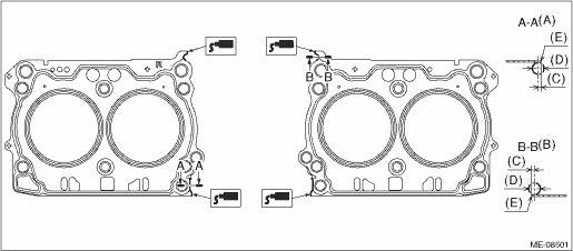
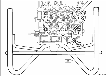
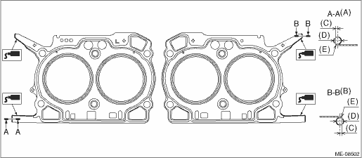
1. CYLINDER HEAD RH 1. Clean the bolt holes in the cylinder block RH. CAUTION: To avoid erroneous tightening of the bolts, clean out the bolt holes sufficiently by blowing with compressed air to eliminate engine coolant etc. 2. Apply liquid gasket to both sides of the cylinder head gasket RH as shown in the figure. NOTE: • Use a new cylinder head gasket RH. • Before applying liquid gasket, degrease the mating surface of cylinder blocks RH and cylinder head RH. • Install within 5 min. after applying liquid gasket. Liquid gasket: THREE BOND 1217G (Part No. K0877Y0100), THREE BOND 1217H or equivalent Liquid gasket applying diameter: 3±1 mm (0.1181±0.0394 in)
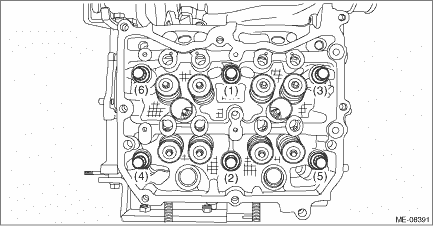
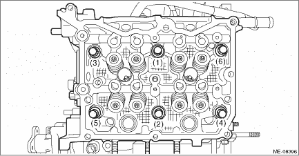
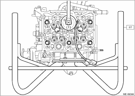
3. Attach the cylinder head gasket RH. NOTE: Check that liquid gasket RH is squeezed out from the cylinder head gasket. 4. Install the cylinder head RH to the cylinder block RH. CAUTION: Be careful not to scratch the mating surface of cylinder head RH and cylinder block RH. (1) Clean the cylinder head bolt threads and apply sufficient engine oil to the washer and cylinder head bolts threads. (2) Mount the cylinder head RH onto the cylinder block RH, and tighten all bolts with a torque of 29 N·m (3.0 kgf-m, 21.4 ft-lb) in numerical order as shown in the figure.
(3) Tighten all cylinder head bolts further with a torque of 100 N·m (10.2 kgf-m, 73.8 ft-lb) in numerical order as shown in the figure. CAUTION: If the bolt makes stick-slip sound during tightening, repeat the procedure from step 1). In that case, the cylinder head gasket RH can be reused. But it is necessary to remove liquid gasket completely from cylinder block RH, cylinder head RH and cylinder head gasket RH and re-apply to them.
(4) Loosen all cylinder head bolts 180° in numerical order as shown in the figure, and then loosen all cylinder head bolts 180° further in numerical order as shown in the figure.
(5) Tighten all cylinder head bolts with a torque of 42 N·m (4.3 kgf-m, 31.0 ft-lb) in numerical order as shown in the figure.
(6) Using angle gauge, tighten all cylinder head bolts with specified angle in numerical order as shown in the figure.
Tightening angle: 80°±2°
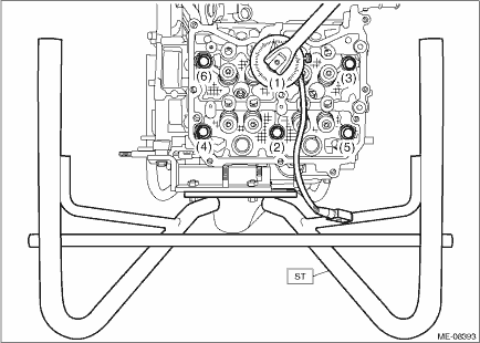
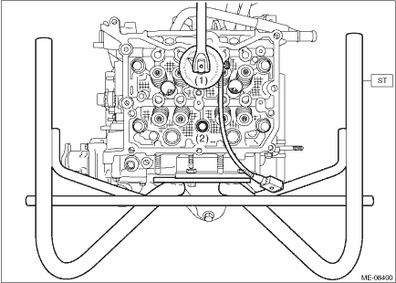
(7) Using angle gauge, tighten the cylinder head bolts (2 places) with specified angle in numerical order as shown in the figure.
Tightening angle: 75°±2°
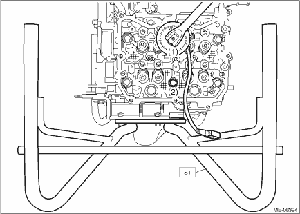
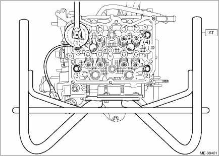
(8) Using angle gauge, tighten the cylinder head bolts (4 places) with specified angle in numerical order as shown in the figure. NOTE: After tightening, if the liquid gasket is squeezed out onto the seal surface of the chain cover, completely remove any squeezed-out liquid gasket.
Tightening angle: 30°±2°
5. Install the EGR cooler. EGR Cooler > INSTALLATION 6. Install the cam carrier RH. Cam Carrier > INSTALLATION 7. Install the rocker cover RH. Rocker Cover > INSTALLATION 8. Install the chain cover. Chain Cover > INSTALLATION 9. Install the engine wiring harness. Engine Wiring Harness > INSTALLATION 10. Install the intake manifold assembly. Intake Manifold Assembly > INSTALLATION 11. Install the engine to the vehicle. Engine Assembly > INSTALLATION 2. CYLINDER HEAD LH 1. Clean the bolt holes in the cylinder block LH. CAUTION: To avoid erroneous tightening of the bolts, clean out the bolt holes sufficiently by blowing with compressed air to eliminate engine coolant etc. 2. Apply liquid gasket to both sides of the cylinder head gasket LH as shown in the figure. NOTE: • Use a new cylinder head gasket LH. • Before applying liquid gasket, degrease the mating surface of cylinder blocks LH and cylinder head LH. • Install within 5 min. after applying liquid gasket. Liquid gasket: THREE BOND 1217G (Part No. K0877Y0100), THREE BOND 1217H or equivalent Liquid gasket applying diameter: 3±1 mm (0.1181±0.0394 in)
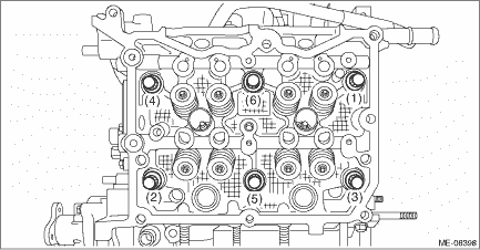
3. Attach the cylinder head gasket LH. NOTE: Check that liquid gasket is squeezed out from the cylinder head gasket LH. 4. Install the cylinder head LH to the cylinder block LH. CAUTION: Be careful not to scratch the mating surface of cylinder head LH and cylinder block LH. (1) Clean the cylinder head bolt threads and apply sufficient engine oil to the washer and cylinder head bolts threads. (2) Mount the cylinder head LH onto the cylinder block LH, then tighten all bolts with a torque of 29 N·m (3.0 kgf-m, 21.4 ft-lb) in numerical order as shown in the figure.
(3) Tighten all cylinder head bolts further with a torque of 100 N·m (10.2 kgf-m, 73.8 ft-lb) in numerical order as shown in the figure. CAUTION: If the bolt makes stick-slip sound during tightening, repeat the procedure from step 1). In that case, the cylinder head gasket LH can be reused. But it is necessary to remove liquid gasket completely from cylinder block LH, cylinder head LH and cylinder head gasket LH and re-apply to them.
(4) Loosen all cylinder head bolts 180° in numerical order as shown in the figure, and then loosen all cylinder head bolts 180° further in numerical order as shown in the figure.
(5) Tighten all cylinder head bolts with a torque of 42 N·m (4.3 kgf-m, 31.0 ft-lb) in numerical order as shown in the figure.
(6) Using angle gauge, tighten all cylinder head bolts with specified angle in numerical order as shown in the figure.
Tightening angle: 80°±2°
(7) Using angle gauge, tighten the cylinder head bolts (2 places) with specified angle in numerical order as shown in the figure.
Tightening angle: 75°±2°
(8) Using angle gauge, tighten the cylinder head bolts (4 places) with specified angle in numerical order as shown in the figure. NOTE: After tightening, if the liquid gasket is squeezed out onto the seal surface of the chain cover, completely remove any squeezed-out liquid gasket.
Tightening angle: 30°±2°
5. Install the A/C compressor. Compressor > INSTALLATION 6. Install the cam carrier LH. Cam Carrier > INSTALLATION 7. Install the rocker cover LH. Rocker Cover > INSTALLATION 8. Install the chain cover. Chain Cover > INSTALLATION 9. Install the engine wiring harness. Engine Wiring Harness > INSTALLATION 10. Install the intake manifold assembly. Intake Manifold Assembly > INSTALLATION 11. Install the engine to the vehicle. Engine Assembly > INSTALLATION |


 Assembly
(1)Exhaust valve(6)Valve spring seat(11)Valve collet(2)Intake valve(7)Intake valve oil seal(12)Valve shim(3)Cylinder head(8)Exhaust valve oil seal(13)Roller rocker arm pivot(4)Intake valve guide(9)Val ...
 Inspection
1. CYLINDER HEAD1. Visually inspect to make sure that there are no cracks, scratches or other damage.2. Use liquid penetrant tester on the important sections to check for fissures.3. Check that there ...
Other materials:
Dtc b16a2 short in front sub sensor rh (to ground)
DIAGNOSIS START CONDITION:Ignition voltage is 10 V to 16 V.DTC DETECTING CONDITION:Shorted between front sub sensor RH circuit and GND circuitWIRING DIAGRAM:NOTE:For the coupling connector, refer to “WIRING SYSTEM”.Airbag system Airbag System > WIRING DIAGRAMSTEPCHECKYESNO1.CHECK POOR C ...
