Subaru Legacy BN/BS (2015-2019) Service Manual: Installation
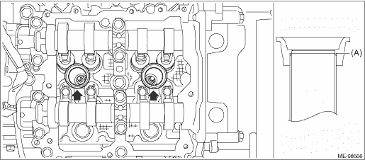
1. ROCKER COVER RH 1. Install the #1 spark plug pipe gasket and #3 spark plug pipe gasket to the #1 spark plug pipe and #3 spark plug pipe. NOTE: • Use a new #1 spark plug pipe gasket and #3 spark plug pipe gasket. • Apply a light coat of engine oil to the #1 spark plug pipe gasket and #3 spark plug pipe gasket, and insert them onto the spark plug pipe edge (A).
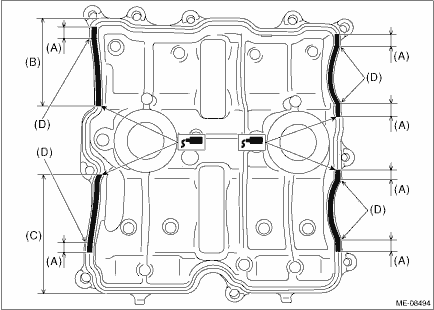
2. Install the rocker cover gasket RH to the rocker cover RH. NOTE: Use a new rocker cover gasket RH. 3. Apply liquid gasket to the mating surface of rocker cover RH as shown in the figure. NOTE: • Before applying liquid gasket, degrease the old liquid gasket seal surface of the engine. • Be careful not to allow liquid gasket to be squeezed out from rocker cover RH. • Install within 5 min. after applying liquid gasket. Liquid gasket: THREE BOND 1217G (Part No. K0877Y0100), THREE BOND 1217H or equivalent Liquid gasket applying diameter: 3.5±0.5 mm (0.1378±0.0197 in)
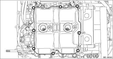
4. Set the rocker cover RH, and tighten the bolts in numerical order as shown in the figure. Tightening torque: 6.4 N·m (0.7 kgf-m, 4.7 ft-lb)
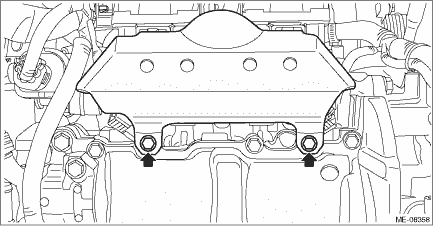
5. Install the intake manifold protector RH. Tightening torque: 6.4 N·m (0.7 kgf-m, 4.7 ft-lb)
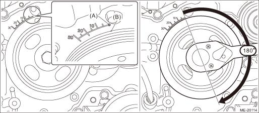
6. Install the #1 ignition coil and the #3 ignition coil. Ignition Coil > INSTALLATION 7. When working on the vehicle NOTE: When working on the vehicle, perform the following steps also. (1) Install the front exhaust pipe. Front Exhaust Pipe > INSTALLATION (2) Install the air cleaner case. Air Cleaner Case > INSTALLATION (3) Install the air intake boot. Air Intake Boot > INSTALLATION 2. ROCKER COVER LH 1. When working on the vehicle NOTE: When working on the vehicle, perform the following steps also. (1) Align the timing mark (B) on crank pulley to the 0° in timing gauge (A) on chain cover as shown in the figure, and turn the crankshaft by 180° clockwise from that position. NOTE: This procedure is required to prevent the rocker cover LH and the cam lobe of camshaft LH contacting with each other when installing the rocker cover LH.
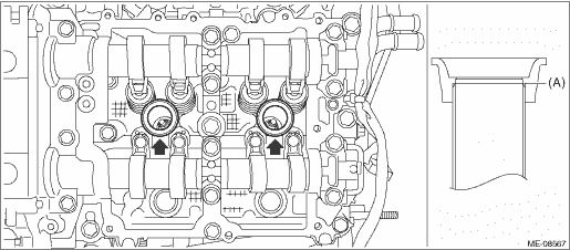
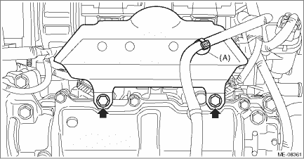
2. Install the #2 spark plug pipe gasket and #4 spark plug pipe gasket to the #2 spark plug pipe and #4 spark plug pipe. NOTE: • Use a new #2 spark plug pipe gasket and #4 spark plug pipe gasket. • Apply a light coat of engine oil to the #2 spark plug pipe gasket and #4 spark plug pipe gasket, and insert them onto the spark plug pipe edge (A).
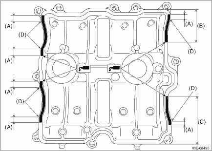
3. Install the rocker cover gasket LH to the rocker cover LH. NOTE: Use a new rocker cover gasket LH. 4. Apply liquid gasket to the mating surface of rocker cover LH as shown in the figure. NOTE: • Before applying liquid gasket, degrease the old liquid gasket seal surface of the engine. • Be careful not to allow liquid gasket to be squeezed out from rocker cover LH. • Install within 5 min. after applying liquid gasket. Liquid gasket: THREE BOND 1217G (Part No. K0877Y0100), THREE BOND 1217H or equivalent Liquid gasket applying diameter: 3.5±0.5 mm (0.1378±0.0197 in)
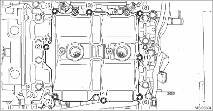
5. Set the rocker cover LH, and tighten the bolts in numerical order as shown in the figure. Tightening torque: 6.4 N·m (0.7 kgf-m, 4.7 ft-lb)
6. Install the intake manifold protector LH and secure the engine harness with the clip (A). Tightening torque: 6.4 N·m (0.7 kgf-m, 4.7 ft-lb)
7. Install the #2 ignition coil and the #4 ignition coil. Ignition Coil > INSTALLATION 8. When working on the vehicle NOTE: When working on the vehicle, perform the following steps also. (1) Install the V-belts. V-belt > INSTALLATION (2) Install the battery. Battery > INSTALLATION |
 Inspection
Check that the rocker cover does not have deformation, cracks and any other damage. ...

Other materials:
Dtc b1655 front buckle switch rh failure
DIAGNOSIS START CONDITION:Ignition voltage is 10 V to 16 V.DTC DETECTING CONDITION:Buckle switch RH failure (open, short, unit failure), seat harness malfunction (open, short), occupant detection system failureWIRING DIAGRAM:Occupant detection system Occupant Detection System > WIRING DIAGRAMSTEPCH ...
