Subaru Legacy BN/BS (2015-2019) Service Manual: Installation
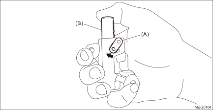
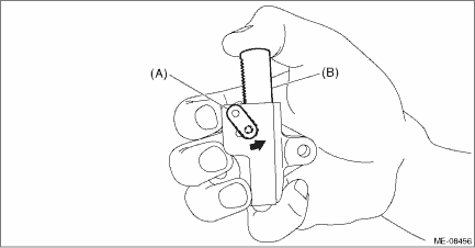
1. TIMING CHAIN LH NOTE: • Be careful that the foreign matter is not into or onto the assembled component during installation. • Apply engine oil to all component parts of the timing chain. 1. Prepare to attach the chain tensioner LH. (1) Move the link plate (A) in the direction of arrow to press in the plunger (B).
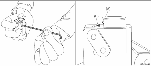
(2) With a 1.3 mm (0.05 in) dia. stopper pin or a 1.3 mm dia. hex wrench inserted into the stopper pin hole, secure the plunger. NOTE: If the stopper pin hole on the link plate and the stopper pin hole on the chain tensioner are not aligned, check that the first notch of plunger rack (A) is engaged with the stopper tooth (B). If not engaged, retract the plunger a little so that the first notch of plunger rack (A) is engaged with the stopper tooth (B).
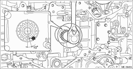
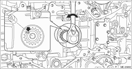
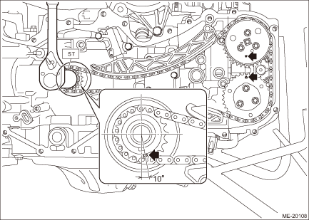
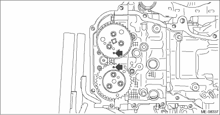
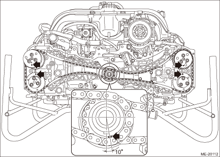
2. Check that the crank sprocket is located at the position shown in the figure. If not aligned, using ST turn the crankshaft to align the crank sprocket alignment mark to the position shown in the figure. NOTE: This procedure is required to prevent the valve and piston contacting with each other in the next step.
3. Using ST and by turning the intake cam sprocket LH, align the alignment marks to the positions as shown in the figure. CAUTION: • When the intake valve and exhaust valve lift at the same time, the valve heads contact each other and valve stem may bend. Do not turn the exhaust camshaft LH. • Perform the operation carefully since the ST comes off easily.
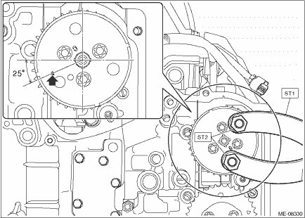
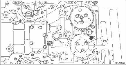
4. Using ST and by turning the crankshaft approximately 200° counterclockwise, align the alignment marks of crankshaft key to the positions as shown in the figure. CAUTION: Never turn clockwise because the valve and piston may contact. Clockwise turn is allowed only when adjusting the key position precisely, after turning the crankshaft counterclockwise to bring the key near the position as shown in the figure.
5. Align the alignment mark of exhaust cam sprocket LH to the position shown in the figure. CAUTION: To prevent valve damage, turn the exhaust cam sprocket LH only within the range of zero-lift (in range where it can be turned lightly by hand).
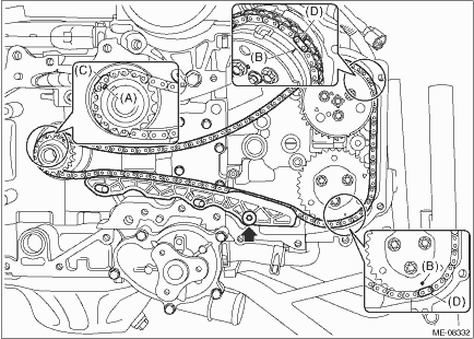
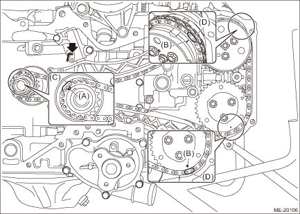
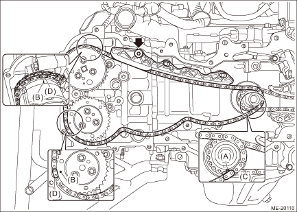
6. Install the timing chain LH and the timing chain guide LH. (1) Match the timing chain mark (blue) to the alignment mark of the crank sprocket. (2) Match the timing chain mark (pink) to the timing mark position of the intake cam sprocket LH. (3) Match the timing chain mark (pink) to the timing mark position of the exhaust cam sprocket LH. (4) Install timing chain guide LH. Tightening torque: 6.4 N·m (0.7 kgf-m, 4.7 ft-lb)
7. Install O-rings to the cylinder block LH. NOTE: Use new O-rings.
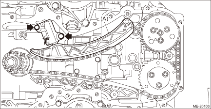
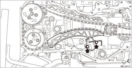
8. Install the chain tensioner lever LH (A) and chain tensioner LH. Tightening torque: 6.4 N·m (0.7 kgf-m, 4.7 ft-lb)
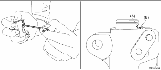
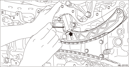
9. Pull out the stopper pin from the chain tensioner LH. CAUTION: Confirm the following before pulling out the stopper pin. • Matching of the timing chain mark (blue) to the alignment mark of the crank sprocket. • Matching of the timing chain mark (pink) to the timing mark position of the intake cam sprocket LH. • Matching of the timing chain mark (pink) to the timing mark position of the exhaust cam sprocket LH. NOTE: If the stopper pin cannot be removed, lift the chain tension lever LH to remove as shown in the figure.
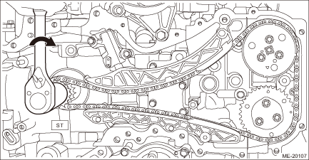
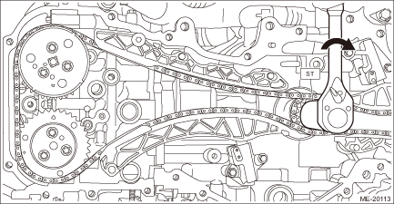
10. Using the ST, turn the crankshaft clockwise, and make sure that there are no abnormal conditions. CAUTION: Always make sure to perform this confirmation.
11. Using ST and by turning the crankshaft, align the alignment marks of crank sprocket, intake cam sprocket LH and exhaust cam sprocket LH to the positions as shown in the figure. NOTE: If the alignment marks are aligned to the positions as shown in the figure, the crankshaft key is located at six o’clock position.
12. Install the timing chain RH. Timing Chain Assembly > INSTALLATION 2. TIMING CHAIN RH NOTE: • Be careful that the foreign matter is not into or onto the assembled component during installation. • Apply engine oil to all component parts of the timing chain. 1. Install timing chain LH. Timing Chain Assembly > INSTALLATION 2. Prepare to attach the chain tensioner RH. (1) Move the link plate (A) in the direction of arrow to press in the plunger (B).
(2) With a 2.5 mm (0.098 in) dia. stopper pin or a 2.5 mm dia. hex wrench inserted into the stopper pin hole, secure the plunger. NOTE: If the stopper pin hole on the link plate and the stopper pin hole on the chain tensioner are not aligned, check that the first notch of plunger rack (A) is engaged with the stopper tooth (B). If not engaged, retract the plunger a little so that the first notch of plunger rack (A) is engaged with the stopper tooth (B).
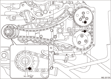
3. Make sure that the alignment marks of the crank sprocket, intake cam sprocket LH and exhaust cam sprocket LH are aligned to the positions as shown in the figure.
4. Align the alignment marks of intake cam sprocket RH and exhaust cam sprocket RH to the positions as shown in the figure. CAUTION: To prevent valve damage, turn the intake cam sprocket RH and exhaust cam sprocket RH only within the range of zero-lift (in range where it can be turned lightly by hand).
5. Install the timing chain RH and the timing chain guide RH. (1) Match the timing chain mark (blue) to the alignment mark of the crank sprocket. (2) Match the timing chain mark (pink) to the timing mark position of the intake cam sprocket RH. (3) Match the timing chain mark (pink) to the timing mark position of the exhaust cam sprocket RH. (4) Install the timing chain guide RH. Tightening torque: 6.4 N·m (0.7 kgf-m, 4.7 ft-lb)
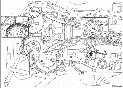
6. Install the chain tensioner lever RH (A) and chain tensioner RH. Tightening torque: 6.4 N·m (0.7 kgf-m, 4.7 ft-lb)
7. Pull out the stopper pin from the chain tensioner RH. CAUTION: Confirm the following before pulling out the stopper pin. • Matching of the timing chain mark (blue) to the alignment mark of the crank sprocket. • Matching of the timing chain mark (pink) to the timing mark position of the intake cam sprocket RH. • Matching of the timing chain mark (pink) to the timing mark position of the exhaust cam sprocket RH.
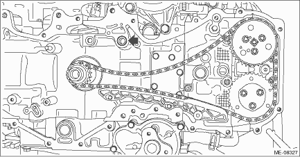
8. Make sure that the alignment marks of the cam sprocket and crank sprocket are aligned to the positions as shown in the figure.
9. Using the ST, turn the crankshaft clockwise, and make sure that there are no abnormal conditions. CAUTION: Always make sure to perform this confirmation.
10. Install the chain cover. Chain Cover > INSTALLATION |
 Inspection
1. Check the timing chain, chain guide, chain tensioner lever and chain tensioner for deformation, cracks or other damages.2. Check the chain guide and chain tensioner lever for abnormal wear. ...
 V-belt
...
Other materials:
Installation
CAUTION:• Do not start the engine before charging refrigerant.• If the engine is started with no refrigerant charge, replace the compressor assembly.• Replace O-rings and pipe clamps with new parts and install securely.• Before handling the airbag system components, refer to ...
