Subaru Legacy BN/BS (2015-2019) Service Manual: Installation
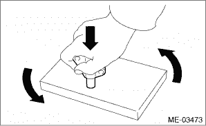
NOTE: • Be careful that the foreign matter is not into or onto the assembled component during installation. • Apply engine oil to all component parts of the timing chain. 1. Prepare to attach the chain tensioner. (1) Insert the screw, spring pin and plunger into the tensioner body. (2) As shown in the figure, turn the rubber mat counterclockwise while holding the chain tensioner from above by hand. NOTE: Degrease the contact surface between the plunger head and rubber mat, so that they do not slip.
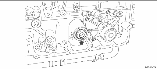
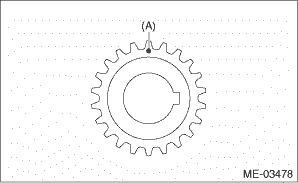
(3) Insert the stopper pin into the hole on the chain tensioner body. 2. Align the position of oil pump shaft knock pin to six o’clock position as shown in the figure.
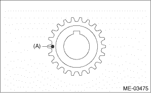
3. Using ST, align the “Top mark” on crank sprocket to nine o’clock position as shown in the figure.
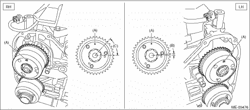
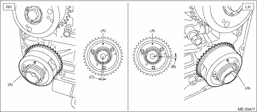
4. Align the intake cam sprocket to twelve o’clock position as shown in the figure.
5. Align the exhaust cam sprocket to twelve o’clock position as shown in the figure.
6. Using ST, align the “Top mark” on crank sprocket to twelve o’clock position as shown in the figure. NOTE: • The #1 piston is positioned at TDC. • Do not rotate the crankshaft and cam sprocket before completing timing chain installation. • At this time, crank sprocket key is at three o’clock position.
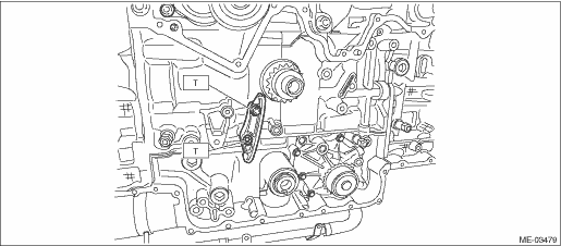
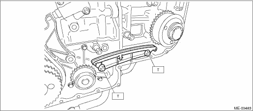
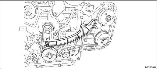
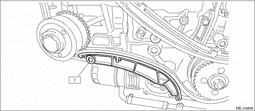
7. Install the chain guide (main). Tightening torque: 16 N·m (1.6 kgf-m, 11.8 ft-lb)
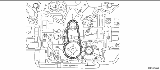
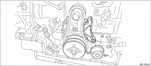
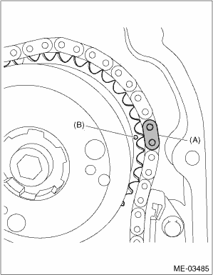
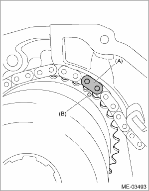
8. Install the idler sprocket and timing chain (main). (1) Match the timing chain mark (gold) to the timing mark position of the idler sprocket. (2) Align the idler sprocket timing mark at six o’clock position, and install the idler sprocket and timing chain. (3) Make sure that the timing chain mark (gold) is located at twelve o’clock position on the crank sprocket. (4) Use the ST to lock the idler sprocket, and install the idler sprocket bolt.
Tightening torque: 120 N·m (12.2 kgf-m, 88.5 ft-lb)
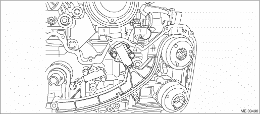
9. Install the chain tensioner lever (main). Tightening torque: 16 N·m (1.6 kgf-m, 11.8 ft-lb)
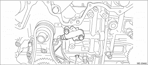
10. Install the chain tensioner (main) and pull out the stopper pin. NOTE: The timing chain (main) line will be complete. Tightening torque: 16 N·m (1.6 kgf-m, 11.8 ft-lb)
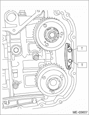
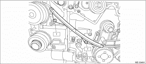
11. Install the chain guide (LH). Tightening torque: 16 N·m (1.6 kgf-m, 11.8 ft-lb)
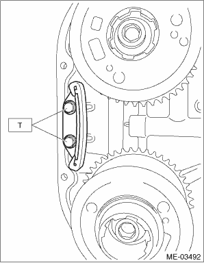
12. Install the chain guide (LH: between cams). Tightening torque: 6.4 N·m (0.7 kgf-m, 4.7 ft-lb)
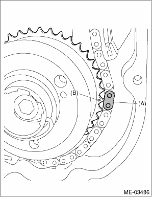
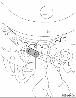
13. Install timing chain (LH). (1) Match the timing mark of intake cam sprocket (LH) to the timing chain mark (blue).
(2) Match the timing mark of exhaust cam sprocket (LH) to the timing chain mark (blue).
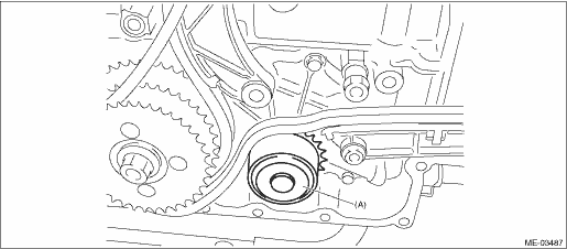
(3) Install the timing chain to the water pump sprocket.
(4) Match the timing mark of idler sprocket to the timing chain mark (gold).
14. Install the chain tensioner lever (LH). Tightening torque: 16 N·m (1.6 kgf-m, 11.8 ft-lb)
15. Install the chain tensioner (LH) and pull out the stopper pin. NOTE: • Make sure that there is a bolt attached on the side face of the chain tensioner housing. • The timing chain (LH) line will be complete. Tightening torque: 16 N·m (1.6 kgf-m, 11.8 ft-lb)
16. Install the chain guide (RH). Tightening torque: 16 N·m (1.6 kgf-m, 11.8 ft-lb)
17. Install the chain guide (RH: between cams). Tightening torque: 6.4 N·m (0.7 kgf-m, 4.7 ft-lb)
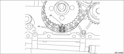
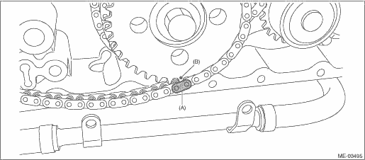
18. Install timing chain (RH). (1) Match the timing mark of intake cam sprocket (RH) to the timing chain mark (blue).
(2) Match the timing mark of exhaust cam sprocket (RH) to the timing chain mark (blue).
(3) Match the timing mark of idler sprocket to the timing chain mark (gold).
19. Install the chain tensioner lever (RH). Tightening torque: 16 N·m (1.6 kgf-m, 11.8 ft-lb)
20. Install the chain tensioner (RH) and pull out the stopper pin. NOTE: The timing chain (RH) line will be complete. Tightening torque: 16 N·m (1.6 kgf-m, 11.8 ft-lb)
21. After installation, perform the following confirmations. CAUTION: Always make sure to perform this confirmation. (1) Make sure that the timing mark of idler sprocket is aligned to three timing chain marks (gold). (2) Make sure that the twelve o’clock position on the crank sprocket is aligned to the timing chain (main) mark (gold). (3) Make sure that the LH side cam sprocket timing mark is aligned to the timing chain mark (blue). (4) Make sure that the RH side cam sprocket timing mark is aligned to the timing chain mark (blue). (5) Make sure that all bolts are tightened at the specified torque. 22. Using the ST, turn the crankshaft in the direction of engine rotation, and make sure that there are no abnormal conditions. CAUTION: Always make sure to perform this confirmation. 23. Install the chain cover. Chain Cover > INSTALLATION 24. Install the crank pulley. Crank Pulley > INSTALLATION 25. Install the V-belts. V-belt > INSTALLATION 26. Fill engine oil. Engine Oil > REPLACEMENT 27. Make sure there is no oil leaks in the chain cover mating surface. 28. Install the radiator. Radiator > INSTALLATION |
 Removal
NOTE:To avoid mixing the timing chain component parts, separate each part after their removal.1. Drain the engine oil. Engine Oil > REPLACEMENT2. Remove the radiator. Radiator > REMOVAL3. Remove the ...
 Location
(1)Chain tensioner (RH)(6)Chain guide (between cams, LH)(11)Chain guide (main)(2)Chain guide (between cams, RH)(7)Chain tensioner lever (LH)(12)Crank sprocket(3)Chain tensioner lever (RH)(8)Chain guid ...
Other materials:
Disassembly
CAUTION:• Use gloves to avoid damage and putting fingerprints on the lens surface and meter surfaces.• Be sure not to touch the meter indicator needle.• Because LEDs are used for all of warning lights and indicator lights, they are not removable from the meter - main assembly.1. Re ...
