Subaru Legacy BN/BS (2015-2019) Service Manual: Installation
NOTE: Use the markings on the glass to apply adhesive and primer, and to install the dam rubber - rear gate and the spacer - rear gate.
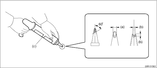
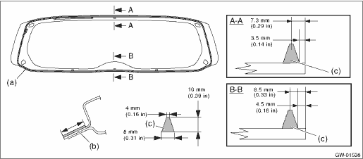
1. Fabricate the cartridge nozzle tip as shown and set the sealant gun with the adhesive.
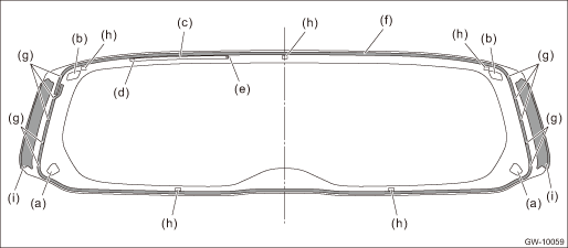
2. Smoothen and clean the adhesive surfaces of the glass - rear gate and body using the same procedures as for the glass - front window. Windshield Glass > INSTALLATION 3. Attach the dam rubber - rear gate to the glass - rear gate.
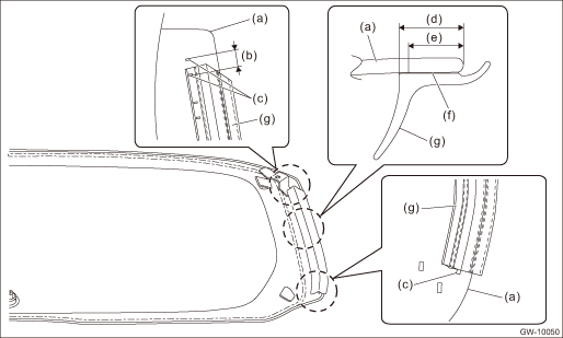
4. Attach the molding - rear gate side to the glass - rear gate. (Model without power rear gate) CAUTION: Be careful to attach the molding - rear gate side so that the molding has no loose or undulating part. NOTE: • Install the molding - rear gate side so that its upper end is within (b). • Use the Ag print as a reference when installing the molding - rear gate side.
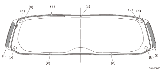
5. Install the glass - rear gate. (1) Apply the primer to the adhesive surface of glass - rear gate side and body side using sponge. (2) Apply adhesive to the glass - rear gate end back surface. CAUTION: Do not apply primer to adhesive.
(3) Attach the holder - clip rear gate to the holder - rear gate upper of the glass - rear gate. (4) Insert the locating pins - rear gate into the rear gate panel holes, and install the glass - rear gate. (5) Lightly press the entire perimeter of the glass - rear gate for tight fit. (6) Make flush the adhesive surface jutted out using spatula. 6. After completion of all work, allow the vehicle to stand for about 24 hours. NOTE: • When opening/closing the door after the glass - rear gate was bonded, always lower the glass assembly - door first, and then open/close it carefully. • Move the vehicle slowly. • For minimum drying time and vehicle standing time before driving after bonding, follow instructions or instruction manual from the adhesive manufacturer. 7. Connect the rear defogger connector. 8. Install the motor assembly - rear wiper and the arm assembly - rear wiper. Rear Wiper Motor > INSTALLATION Tightening torque: Motor assembly - rear wiper and arm assembly - rear wiper: General Description > COMPONENT 9. Install the roof spoiler. Rear Gate Garnish > INSTALLATION Tightening torque: 7.5 N·m (0.8 kgf-m, 5.5 ft-lb) 10. Install the touch sensor LWR. Power Rear Gate Touch Sensor > INSTALLATION 11. Install the trim panel - rear gate. Rear Gate Trim > INSTALLATION 12. Connect the ground terminal to battery sensor. NOTE 13. After curing of adhesive, pour the water on external surface of vehicle to check that there are no water leaks. NOTE: When a vehicle is returned to the user, tell him or her that the vehicle should not be subjected to heavy impact for at least three days. |
 Removal
1. Disconnect the ground terminal from battery sensor. NOTE2. Remove the roof spoiler. Roof Spoiler > REMOVAL3. Remove the trim panel - rear gate and the motor assembly - rear wiper. Rear Wiper Mot ...

Other materials:
Electrical
Model2.5 L DOHC non-turbo3.6 L DOHC non-turboIgnition timing (at idling)BTDCCVT: 5°±10°MT: 6°±10°15°±8°Spark plugType and manufacturerNGK: SILZKAR7B11NGK: SILFR6C11Generator12 V — 130 ABatteryType and capacity (5HR)12 V — 48AH (55D23R)12 V — 52AH (7 ...
