Subaru Legacy BN/BS (2015-2019) Service Manual: Refrigerant charging procedure procedure
CAUTION: • While working, be sure to wear protective goggles and protective gloves. • Air in the cycle can cause insufficient air conditioning, and water in the cycle can cause clogging in the cycle (icing) and rust. To remove this air and water content, use a vacuum pump to perform evacuation before filling with refrigerant. By making the inside of the cycle a vacuum, the water content will evaporate even at normal temperatures, and can be removed.
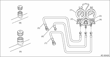
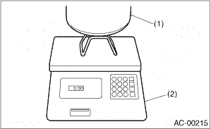
1. Attach the manifold gauge set. Preparation tool: Manifold gauge set (1) Check that all valves are fully closed. (2) Install the low/high pressure hoses to the service ports on the low/high pressure sides of the vehicle respectively. CAUTION: Confirm that the connections are secure. (3) Connect the center manifold hose of the manifold gauge to the vacuum pump. Preparation tool: Vacuum pump 2. Perform evacuation. CAUTION: Make sure to perform evacuation using a vacuum pump. (1) Open the low-pressure valve, high-pressure valve and center valve. (2) Operate the vacuum pump. (3) Perform evacuation for 5 minutes or more, and when the low pressure gauge needle reaches -0.1 MPa (-1 kgf/cm2, −14 psi), close the center manifold hose valve, and stop the vacuum pump. (4) Leave alone for 5 to 10 minutes after closing the low pressure and high pressure valves, and check whether there is any change in the low pressure gauge needle indication. If the needle position changes, this indicates a leak. Check the pipe and hose connections, and repair the location with the problem. After repair, retry charging the refrigerant from the step 1). (5) If there is no leakage, continue evacuation for additional 20 — 30 minutes, close all valves and then stop the vacuum pump. 3. Charge refrigerant. (1) Follow the can tap operation manual to attach it to the refrigerant can. Preparation tool: Can tap (2) Disconnect the center manifold hose from the vacuum pump, and connect the hose to the tap valve. Preparation tool: Weight scale NOTE: When 13.6 kg (30 lb) refrigerant container (1) is used, measure the amount of refrigerant with a refrigerant charging scale (2), and connect with the center manifold hose.
(3) Open the tap valve of HFC-134a supply container (refrigerant can or refrigerant container). (4) Loosen the center manifold hose connection on the manifold gauge for a few seconds (if there is a purge valve on the manifold gauge, push this instead) to allow the air in the center manifold hose to be bled by the refrigerant pressure. (5) Open the high pressure and low pressure valves of the manifold gauge to fill with refrigerant. NOTE: If the HFC-134a supply container is empty, close all manifold gauge valves and the tap valve of HFC-134a supply container, and replace the empty supply container with a new one. After replacing with a new HFC-134a supply container, perform air purge, and resume the filling operation. (6) If the low pressure gauge indicates approximately 0.2 MPa (2 kgf/cm2, 29 psi) or refrigerant filling efficiency drops, close the low pressure and high pressure valves. (7) Check that the low pressure and high pressure valves are closed, turn off the A/C switch and start the engine. CAUTION: When filling operation is performed with the engine running, do not open the high pressure valve. Always fill from the low pressure valve. (8) To prevent damage to the compressor, push the A/C switch ON-OFF quickly a few times. (9) Set the vehicle to the following conditions.
(10) Open the low pressure valve, check the refrigerant pressure with a manifold gauge and fill with refrigerant up to the specified amount. Refrigerant Pressure with Manifold Gauge Set > INSPECTION 4. Using an electronic leak detector (leak tester), check for refrigerant leaks in the system. Refrigerant Leak Check > INSPECTION 5. After filling with refrigerant, close all valves and remove the manifold gauge set. 6. Attach cap to the service port of the low pressure side and high pressure side. |
 Pressure sensor inspection
1. Perform a diagnosis code (DTC) check by connecting the Subaru Select Monitor. Read Diagnostic Trouble Code (DTC) > OPERATION2. If any diagnosis code (DTC) is displayed, refer to “List of Dia ...
 Refrigerant leak check inspection
1. Attach the manifold gauge set.Preparation tool:Manifold gauge set(1) Check that all valves are fully closed.(2) Install the low/high pressure hoses to the service ports on the low/high pressure sid ...
Other materials:
List
ItemContent / display rangeTrip CountTime stamp information General Description > CAUTIONCountTime CountBATT voltageImmobilizer CM battery voltageIgnition SW inputIgnition switch statuskey-lock warning SW InputKey warning switch statusImmobilizer indicator outputSecurity indicator output statusImmob ...
