Subaru Legacy BN/BS (2015-2019) Service Manual: Removal
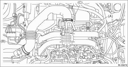
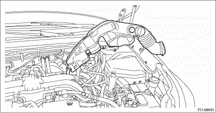
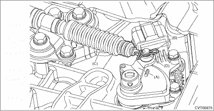
1. Disconnect the ground terminal from battery sensor. NOTE 2. Lock the steering wheel. 3. Remove the air intake duct. Air Intake Duct > REMOVAL 4. Remove the clip (A), and loosen the clamps (B) and (C).
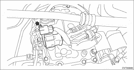
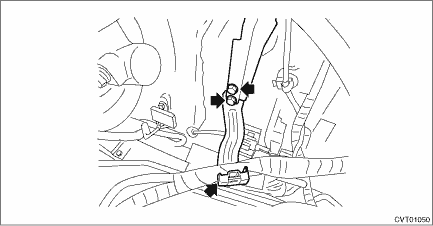
5. Remove the air intake boot from the throttle body, and move it to the left side wheel apron, etc.
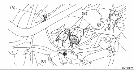
6. Disconnect the transmission radio ground terminal and transmission harness connector, and remove the harness clip.
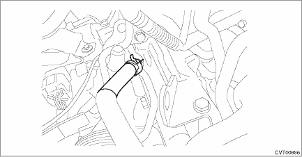
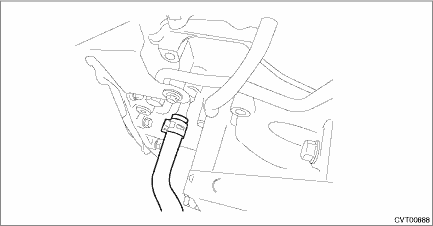
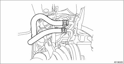
7. Remove the CVTF cooler hose. (With CVTF cooler (air cool))
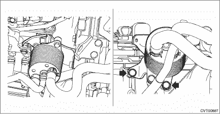
8. Remove the CVTF cooler (with warmer feature), and using a piece of wire, affix to a location of the body where it will not interfere with the removal/installation of the transmission.
9. Remove the CVTF inlet hose and outlet hose. (Without CVTF cooler (air cool))
10. Remove the CVTF outlet hose. (With CVTF cooler (air cool))
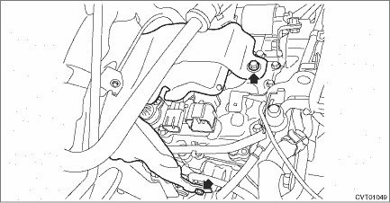
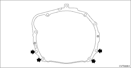
11. Remove the transmission case cover.
12. Remove the TCM. Transmission Control Module (TCM) > REMOVAL 13. Remove the transmission harness stay.
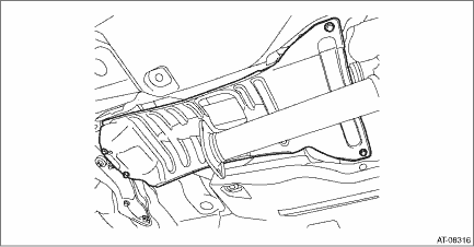
14. Remove the front tire LH and RH. 15. Lift up the vehicle. 16. Remove the under cover - front. 17. Remove the CVTF drain plug to drain CVTF. CVTF > REPLACEMENT 18. Drain differential gear oil. Differential Gear Oil > REPLACEMENT 19. Remove the center exhaust pipe (rear). Center Exhaust Pipe > REMOVAL 20. Remove the center exhaust cover.
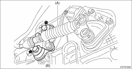
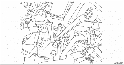
21. Remove the propeller shaft. Propeller Shaft > REMOVAL 22. Remove the snap pin and washer from shifter arm and remove the select cable.
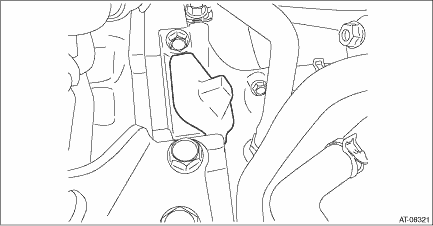
23. Remove the plate assembly.
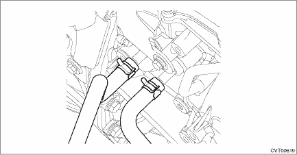
24. Remove the CVTF CVT inlet hose and CVTF CVT outlet hose. (With CVTF cooler (air cool))
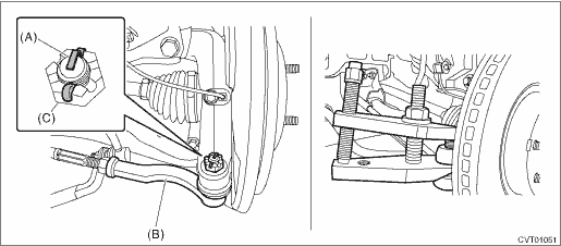
25. Remove the universal joint. Universal Joint > REMOVAL 26. After pulling off the cotter pin and removing the castle nut, use a puller to remove the tie-rod end. NOTE: Use a tool appropriate to the structure, and be careful not to damage the boot of the joint while removing. The boot may be damaged depending on the tool used.
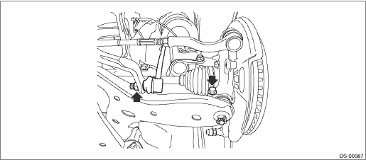
27. Remove the stabilizer link, and disconnect the lower arm ball joint and housing.
28. Pull out the front drive shaft from transmission using a crowbar. NOTE: Holding the joint of front drive shaft from transmission side, pull out the drive shaft from transmission with care not to stretch the boot. 29. Loosen the bolt at the bottom of the transmission mounting bracket.
30. Lower the vehicle. 31. Detach the battery cable clip, and remove the battery cable bracket.
32. Remove the starter. Starter > REMOVAL 33. Remove the service hole plug.
34. Remove the four bolts combining the torque converter and drive plate while rotating the crank pulley a little at a time in the same direction as engine revolution. CAUTION: • Be careful not to drop bolts into converter housing. • Be careful not to damage the mounting bolts.
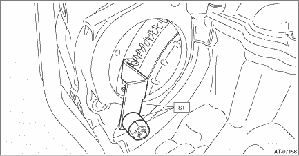
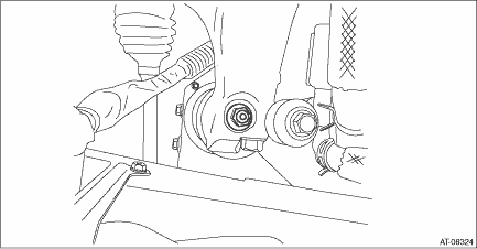
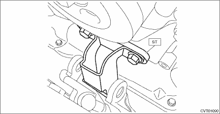
35. Make sure the torque converter moves freely by rotating with finger through the starter installation hole. 36. Attach the ST to the converter case.
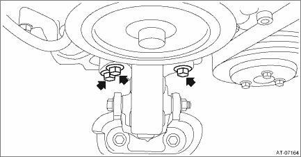
37. Remove the nuts from the transmission mounting brackets LH and RH.
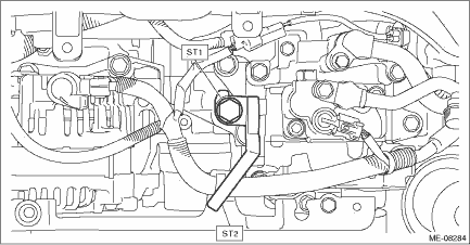
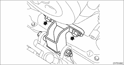
38. Remove the V-belt covers. 39. Set the ST to the engine.
Tightening torque: 43 N·m (4.4 kgf-m, 31.7 ft-lb)
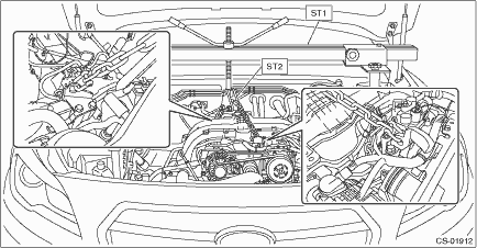
40. Set the ST1 and ST2 to vehicle.
CAUTION: • Set so that the chain sling does not contact the engine parts. • Install a bolt of φ8 mm (0.3 in) at the locations shown in the figure, and place the front side arms of ST (ENGINE HANGER). • Set the arms of ST (ENGINE HANGER) at the locations shown in the figure.
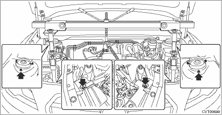
41. Lift the engine slightly and remove the engine mounting bolts.
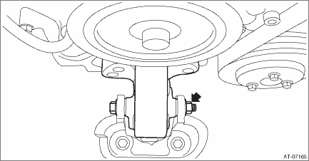
42. Remove the engine mounting nut and bolt to remove the front cushion rubber.
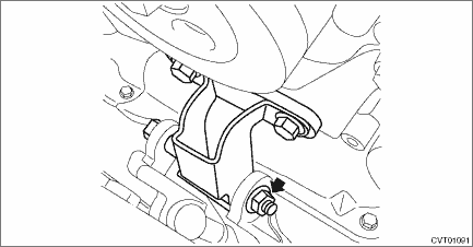
43. Temporarily attach ST by using two bolts.
44. Lift up the engine unit high enough to install the bolt and nut. CAUTION: Do not lift up higher than enough level to install the ST to avoid damage to the hoses and pipes inside the engine room. NOTE: If it is difficult to pull out the stud bolt from transmission mounting bracket, slightly shake the engine unit while lifting up.
45. Tighten the mounting bolts on the engine side. Tightening torque: 25 N·m (2.5 kgf-m, 18.4 ft-lb)
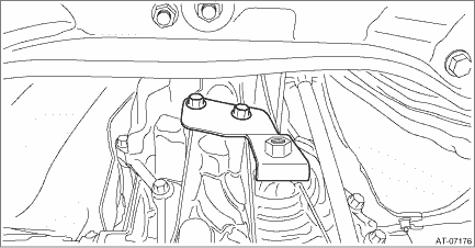
46. Remove the ST (ENGINE HANGER). 47. Remove the transmission mounting bracket LH and RH. NOTE: First, remove the transmission mounting bracket RH, and then tilt the engine unit to remove the transmission mounting bracket LH.
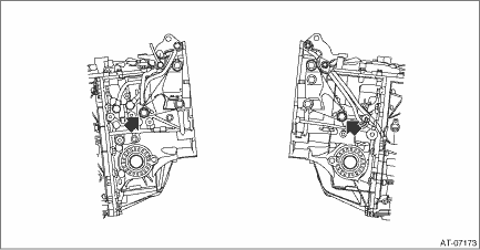
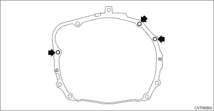
48. Remove the three transmission connecting bolts.
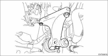
49. Set the ST (ENGINE HANGER) again to loosen the chain sling. 50. Lift up the vehicle. 51. Set the transmission jack under the transmission. 52. Remove the hanger bracket.
53. Remove the rear crossmember. Transmission Mounting System > INSTALLATION 54. Lower the transmission rear end (dust cover rear end). CAUTION: When lowering the transmission rear end, be careful not to let the converter case and steering mechanical parts contact each other. NOTE: Lower the transmission rear end by approx. 80 mm (3.1 in) (reference). 55. Rotate the handle of ST (ENGINE HANGER) to apply tension to the chain sling. 56. Remove the two transmission connecting bolts and two nuts (lower side).
57. Remove the transmission assembly. NOTE: Remove it while moving the transmission jack up and down so that the engine and transmission axes are aligned straight. 58. Remove the cushion rubber. Transmission Mounting System > REMOVAL |

 Installation
1. Attach the ST to converter case.ST 498277200STOPPER SET2. Replace the front differential side retainer oil seal. Differential Side Retainer Oil Seal > REPLACEMENTNOTE:• Be sure to replace ...
Other materials:
Inspection
1. Check the motor operation when battery voltage is applied between the connector terminals.• LH sideTerminal No.Inspection conditionsStandard6 (+) — 3 (−)Apply battery voltage between terminals.Increase3 (+) — 6 (−)Apply battery voltage between terminals.Decrease• RH si ...
