Subaru Legacy BN/BS (2015-2019) Service Manual: Removal
1. Remove the transmission assembly. Automatic Transmission Assembly > REMOVAL 2. Remove the air breather hose. Air Breather Hose > REMOVAL 3. Remove the control valve body. Control Valve Body > REMOVAL 4. Remove the transmission harness. Transmission Harness > REMOVAL 5. Remove the turbine speed sensor. Turbine Speed Sensor > REMOVAL 6. Remove the secondary speed sensor. Secondary Speed Sensor > REMOVAL 7. Remove the primary speed sensor. Primary Speed Sensor > REMOVAL 8. Remove the inhibitor switch. Inhibitor Switch > REMOVAL 9. Remove the extension case. Extension Case > REMOVAL 10. Remove the transfer clutch assembly. Transfer Clutch > REMOVAL 11. Remove the transfer driven gear assembly. Transfer Driven Gear > REMOVAL 12. Remove the parking pawl. Parking Pawl > REMOVAL 13. Remove the reduction driven gear assembly. Reduction Driven Gear > REMOVAL 14. Remove the oil pan and oil strainer. Oil Pan and Strainer > REMOVAL 15. Remove the transmission control device. Transmission Control Device > REMOVAL 16. Remove the transmission case. Transmission Case > REMOVAL 17. Remove the reduction drive gear. Reduction Drive Gear > REMOVAL 18. Remove the primary pulley, secondary pulley and variator chain. Primary Pulley and Secondary Pulley > REMOVAL 19. Remove the manual valve assembly and separator plate.
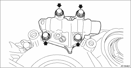
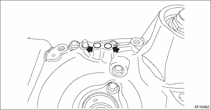
20. Remove the oil guide and lubrication pipe.
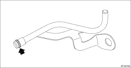
21. Remove the O-ring from lubrication pipe.
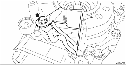
22. Remove the reverse brake assembly.
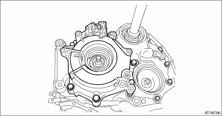
23. Remove the O-rings.
|

 Assembly
1. Install the reverse brake piston.NOTE:Apply CVTF to the sealing area of reverse brake piston.2. Install the return spring.3. Install the spring retainer.4. Compress the return spring using the ST t ...
Other materials:
Electrical specification
• Terminal numbers in airbag control module connector are shown in the figure.• The airbag warning light illuminates when the connector is removed from the airbag control module.Terminal No.Content(AB6) No. 1Driver’s airbag module, 2nd stage +(AB6) No. 2Driver’s airbag module ...
