Subaru Legacy BN/BS (2015-2019) Service Manual: Removal
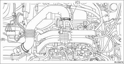
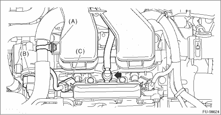
1. Release the fuel pressure. Fuel > PROCEDURE 2. Disconnect the ground terminal from battery sensor. NOTE 3. Open the fuel filler lid and remove the fuel filler cap. NOTE: This operation is required to release the inner pressure of the fuel tank. 4. Drain approximately 3.0 L (3.2 US qt, 2.6 Imp qt) of coolant. Engine Coolant > REPLACEMENT 5. Remove the clip (A), and loosen the clamps (B) and (C) securing the air intake boot.
6. Remove the air intake boot from the air cleaner case (rear) and throttle body, and move it to the left side wheel apron.
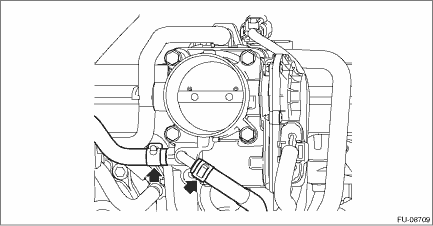
7. Disconnect the preheater hose from throttle body.
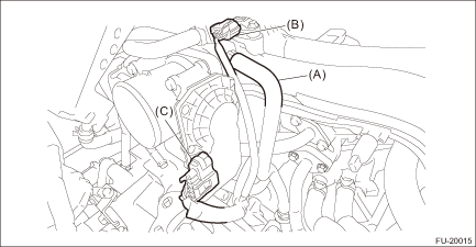
8. Disconnect the PCV hose (A) from intake manifold assembly. 9. Disconnect the connector (B) from manifold absolute pressure sensor. 10. Disconnect the connector (C) from throttle body.
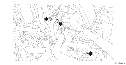
11. Remove the bolt securing the EGR cooler to the EGR control valve. 12. Loosen the bolts holding the EGR cooler to the cylinder head RH.
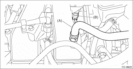
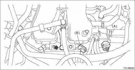
13. Disconnect the brake booster vacuum hose (A), and disconnect the connector (B) from the purge control solenoid valve.
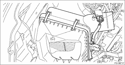
14. Remove the air intake duct. Air Intake Duct > REMOVAL 15. Disconnect the connector (A) from the mass air flow and intake air temperature sensor, and remove the clip (B) securing the bulkhead wiring harness. 16. Remove the clip (C), and the air cleaner case (rear) together with the air cleaner element.
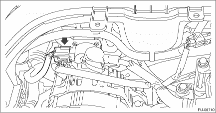
17. Disconnect the connector from the EGR control valve.
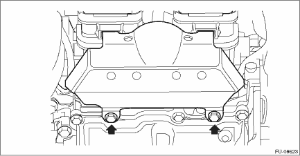
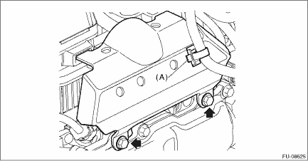
18. Remove the intake manifold protector RH.
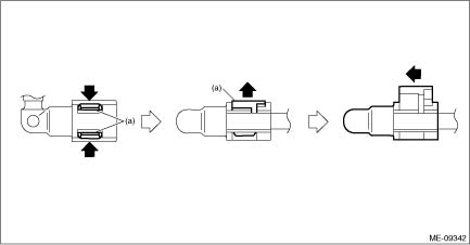
19. Remove the clip (A) securing the engine harness to the intake manifold assembly, and disconnect the connector (B) from the tumble generator valve and disconnect the connector (C) from the fuel injector #3. 20. Disconnect the fuel delivery pipe from the fuel pipe RH. CAUTION: • Be careful not to spill fuel. • Catch the fuel from the pipes using a container or cloth. NOTE: Disconnect the quick connector as shown in the figure.
21. Remove the clip (A) securing the engine harness to the intake manifold protector LH to remove the intake manifold protector LH.
22. Disconnect the connector (A) from the tumble generator valve, and disconnect the connector (B) from the fuel injector #4. 23. Disconnect the fuel delivery pipe from the fuel pipe LH. CAUTION: • Be careful not to spill fuel. • Catch the fuel from the pipes using a container or cloth. NOTE: Disconnect the quick connector as shown in the figure.
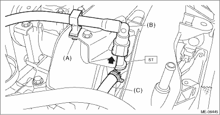
24. Disconnect the fuel delivery tube and evaporation hose. CAUTION: • Be careful not to spill fuel. • Catch the fuel from the tubes using a container or cloth. (1) Remove the clip (A) securing the fuel delivery tube. (2) Attach ST to the fuel pipe assembly and push ST in the direction of arrow mark to disconnect the quick connector of the fuel delivery tube (B).
(3) Disconnect the evaporation hose (C) from the fuel pipe assembly.
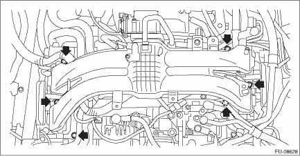
25. Remove the intake manifold assembly from cylinder head.
|


 Assembly
1. Install the fuel pipe assembly to the intake manifold assembly.Tightening torque:6.4 N·m (0.7 kgf-m, 4.7 ft-lb)2. Install the fuel delivery pipe to the intake manifold assembly.CAUTION:&bull ...
Other materials:
Note
• The on-board diagnostic (OBD) system detects and indicates a fault in various inputs and outputs of the complex electronic control. Malfunction indicator light in the combination meter indicates occurrence of a fault or trouble.• Further, against any failure of sensors that would cause ...
