1. HEATER SYSTEM Item | Specifications | Condition | Heating capacity | 4.8 kW (4,127 kcal/h, 16,377 BTU/h) or more | • Air flow control switch: FOOT • Temperature control dial: HI (MAX HOT) • Temperature difference between hot water and inlet air: 65°C (149°F) • Hot water flow rate: 360 L (95.1 US gal, 79.2 Imp gal)/h | Air flow rate | 300 m3 (10,596 cu ft)/h | FOOT mode (FRESH), MAX HOT at 12.5 V | Max air flow rate | 495 m3 (17,483 cu ft)/h | • Temperature control dial: LO (MAX COOL) • Fan switch or dial: HI (MAX) – Auto A/C model: 7th position – Manual A/C model: 4th position • FRESH/RECIRC switch: RECIRC | Heater core size (height - length - width) | 264 - 100 - 27 mm (10.4 - 3.94 - 1.06 in) | — | Blower motor | Type | Magnet motor 260 W or less | 12 V | Fan type and size (diameter - width) | Sirocco fan type 150 - 75 mm (5.91 - 2.95 in) | — |
2. A/C SYSTEM Item | Specifications | Type of air conditioner | Reheat air-mix type | Cooling capacity | 4.18 kW [at 500 m3 (17,660 cu ft)/h] (3,594 kcal/h, 14,262 BTU/h) | Refrigerant | HFC-134a (CH2FCF3) [0.425±0.025 kg (0.94±0.06 lb)] | Compressor | Type | H4 model: Swash plate, variable volume (TSE14F) H6 model: Swash plate, variable volume (TSE14C) | Discharge | 140.6 cc (8.58 cu in)/rev | Max. permissible speed | 6,000 r/min | Pulley | Type of belt | V-belt 6 PK | Pulley dia. (effective dia.) | 110 mm (4.33 in) | Pulley ratio | 1.3 | Condenser | Type | Corrugated fin (sub cool type) | Core face area | 0.186 m2 (2.002 sq ft) | Core thickness | 11.5 mm (0.45 in) | Radiation area | 3.516 m2 (37.85 sq ft) | Receiver drier | Effective inner capacity | 190 cm3 (11.6 cu in) | Expansion valve | Type | Internally equalizing | Evaporator | Type | Double tank | Dimensions (W - H - T) | 293.1 - 171 - 38 mm (11.54 - 6.73 - 1.5 in) | Blower fan | Fan type | Sirocco fan | Outer diameter - Width | 150 - 75 mm (5.91 - 2.95 in) | Power consumption | 260 W | Condenser fan (sub fan) | Motor type | Magnet | Power consumption | H4 model: 120 W H6 model: 240 W | Fan outer diameter | 320 mm (12.6 in) | Radiator fan (main fan) | Motor type | Magnet | Power consumption | H4 model: 120 W H6 model: 240 W | Fan outer diameter | 320 mm (12.6 in) | Idle speed | MPFI model | No load | H4 MT model: 650±100 r/min H4 CVT model: 675±100 r/min H6 model: 700±100 r/min | A/C ON | H4 MT model: 800 — 850±100 r/min H4 CVT model: 700±100 r/min H6 model: 700 — 910±100 r/min |
3. BASIC OPERATION The cooling system cools down the compartment by using the pipes connecting parts and cycling the evaporable liquid (refrigerant) within the sealed system in a repeated process of “vaporization — liquefaction — re-vaporization”. 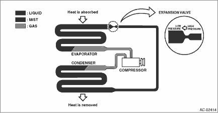
Item | Operation | Compressor | Sucks and pressurizes the low temperature, low pressure refrigerant gas that was vaporized at the evaporator by absorbing heat from the compartment, and sends the high temperature, high pressure refrigerant gas to the condenser. | Condenser | Cools the high temperature, high pressure refrigerant gas sent from the compressor for condense and liquefaction. | Expansion valve | • Sprays the high temperature, high pressure liquid refrigerant from the small hole in order to let the refrigerant expand rapidly to turn it into low temperature, low pressure mist. • The refrigerant amount is adjusted according to the refrigerant vaporization condition in the evaporator. | Evaporator | The evaporator turns into a low temperature condition when the mist refrigerant that was turned into a low temperature, low pressure condition at the expansion valve is vaporized in large quantity in the evaporator. Passing air flow through the low temperature evaporator emits cold air. |
|

 Caution