Subaru Legacy BN/BS (2015-2019) Service Manual: Dtc p0131 a/f / o2 sensor circuit low voltage bank 1 sensor 1
DTC DETECTING CONDITION: Immediately at fault recognition CAUTION: After servicing or replacing faulty parts, perform Clear Memory Mode Clear Memory Mode > OPERATION, and Inspection Mode Inspection Mode > PROCEDURE. WIRING DIAGRAM: • Engine Electrical System ENGINE TYPE EZ (WITHOUT PUSH BUTTON START) Engine Electrical System > WIRING DIAGRAM • Engine Electrical System ENGINE TYPE EZ (WITH PUSH BUTTON START) Engine Electrical System > WIRING DIAGRAM
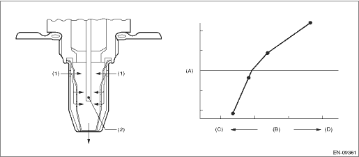
1. OUTLINE OF DIAGNOSIS Detect the open or short circuit of sensor. Judge as NG, when the element voltage is out of the specified range. 2. COMPONENT DESCRIPTION
3. EXECUTION CONDITION
4. GENERAL DRIVING CYCLE Always perform the diagnosis continuously. 5. DIAGNOSTIC METHOD If the duration of time while the following conditions are met is longer than the time indicated, judge as NG.
Time Needed for Diagnosis: (1): 1000 ms (2): 1000 ms (3): 1000 ms Malfunction Indicator Light Illumination: Illuminates as soon as a malfunction occurs. |

 Dtc p0132 a/f / o2 sensor circuit high voltage bank 1 sensor 1
DTC DETECTING CONDITION:Immediately at fault recognitionCAUTION:After servicing or replacing faulty parts, perform Clear Memory Mode Clear Memory Mode > OPERATION, and Inspection Mode Inspection Mod ...
 Dtc p0123 throttle/pedal position sensor/switch "a" circuit high
DTC DETECTING CONDITION:Immediately at fault recognitionTROUBLE SYMPTOM:• Improper idling• Engine stalls.• Poor driving performanceCAUTION:After servicing or replacing faulty parts, ...
Other materials:
Removal
1. Disconnect the ground terminal from battery sensor. NOTE2. Drain approximately 3.0 L (3.2 US qt, 2.6 Imp qt) of coolant. Engine Coolant > REPLACEMENT3. Remove the clip (A), and loosen the clamps (B) and (C) securing the air intake boot.4. Remove the air intake boot from the air cleaner case (re ...
