Subaru Legacy BN/BS (2015-2019) Service Manual: Dtc p013a o2 sensor slow response - rich to lean bank 1 sensor 2
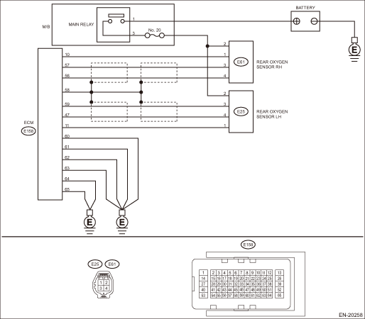
DTC DETECTING CONDITION: Detected when two consecutive driving cycles with fault occur. CAUTION: After servicing or replacing faulty parts, perform Clear Memory Mode Clear Memory Mode > OPERATION, and Inspection Mode Inspection Mode > PROCEDURE. WIRING DIAGRAM: • Engine Electrical System ENGINE TYPE EZ (WITHOUT PUSH BUTTON START) Engine Electrical System > WIRING DIAGRAM • Engine Electrical System ENGINE TYPE EZ (WITH PUSH BUTTON START) Engine Electrical System > WIRING DIAGRAM
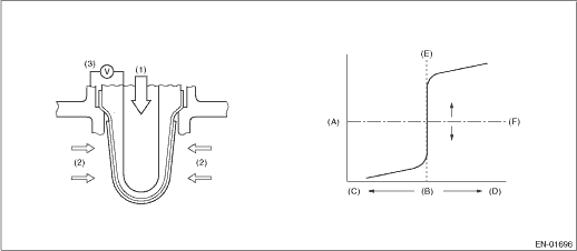
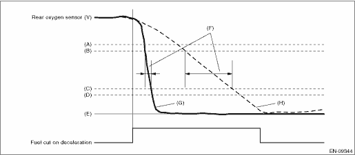
1. OUTLINE OF DIAGNOSIS Detect the slow response of rich > lean for rear oxygen sensor output. When the deceleration fuel cut has occurred, detect the trouble by calculating the time when the rear oxygen sensor output passes through the predetermined range of voltages. Judge as NG when the response time is larger than the threshold value. 2. COMPONENT DESCRIPTION
3. EXECUTION CONDITION
4. GENERAL DRIVING CYCLE Perform the diagnosis only once when the deceleration fuel cut is activated from a high and constant speed driving. 5. DIAGNOSTIC METHOD Detect the trouble by calculating the response time of the rear oxygen sensor during fuel cut.
Judge as NG when the following conditions are established.
Time Needed for Diagnosis: 5000 ms Malfunction Indicator Light Illumination: Illuminates when malfunction occurs in 2 continuous driving cycles. |
 Dtc p013b o2 sensor slow response - lean to rich bank 1 sensor 2
NOTE:For the diagnostic procedure, refer to DTC P013A. Diagnostic Procedure with Diagnostic Trouble Code (DTC) > DTC P013A O2 SENSOR SLOW RESPONSE - RICH TO LEAN BANK 1 SENSOR 21. OUTLINE OF DIAGNOSI ...
 Dtc p0138 o2 sensor circuit high voltage bank 1 sensor 2
DTC DETECTING CONDITION:Detected when two consecutive driving cycles with fault occur.CAUTION:After servicing or replacing faulty parts, perform Clear Memory Mode Clear Memory Mode > OPERATION, and I ...
Other materials:
Dtc u1712 lost lin communication with battery "1" monitor module
DTC DETECTING CONDITION:Immediately at fault recognitionCAUTION:After servicing or replacing faulty parts, perform Clear Memory Mode Clear Memory Mode > OPERATION, and Inspection Mode Inspection Mode > PROCEDURE.WIRING DIAGRAM:• Engine Electrical System ENGINE TYPE FB (WITHOUT PUSH BUTTON ST ...
