
Subaru Legacy BN/BS (2015-2019) Service Manual: Dtc p2195 a/f /o2 sensor signal biased/stuck lean bank 1 sensor 1
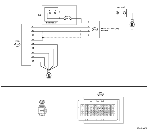
DTC DETECTING CONDITION: Detected when two consecutive driving cycles with fault occur. CAUTION: After servicing or replacing faulty parts, perform Clear Memory Mode Clear Memory Mode > OPERATION, and Inspection Mode Inspection Mode > PROCEDURE. WIRING DIAGRAM: • Engine Electrical System ENGINE TYPE FB (WITHOUT PUSH BUTTON START) Engine Electrical System > WIRING DIAGRAM • Engine Electrical System ENGINE TYPE FB (WITH PUSH BUTTON START) Engine Electrical System > WIRING DIAGRAM
1. OUTLINE OF DIAGNOSIS Detect that λ value remains low. Judge as NG if the lambda value can be determined as abnormal in accordance with driving conditions such as vehicle speed, intake air amount, and rear oxygen sensor voltage as well as front oxygen (A/F) sensor λ value.
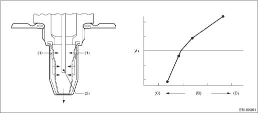
2. COMPONENT DESCRIPTION
3. EXECUTION CONDITION
4. GENERAL DRIVING CYCLE Perform the diagnosis continuously after the enable conditions have been established. 5. DIAGNOSTIC METHOD If the duration of time while the following conditions are met is longer than the time indicated, judge as NG.
Time Needed for Diagnosis: 10000 ms Malfunction Indicator Light Illumination: Illuminates when malfunction occurs in 2 continuous driving cycles. |
 Dtc p2196 a/f /o2 sensor signal biased/stuck rich bank 1 sensor 1
DTC DETECTING CONDITION:Detected when two consecutive driving cycles with fault occur.CAUTION:After servicing or replacing faulty parts, perform Clear Memory Mode Clear Memory Mode > OPERATION, and I ...
 Dtc p2138 throttle/pedal position sensor/switch "d"/"e" voltage correlation
DTC DETECTING CONDITION:Immediately at fault recognitionTROUBLE SYMPTOM:• Improper idling• Poor driving performanceCAUTION:After servicing or replacing faulty parts, perform Clear Memory M ...
Other materials:
Road test inspection
1. GENERAL PRECAUTIONRoad tests should be conducted to properly diagnose the condition of CVT.CAUTION:Always observe the local traffic laws when performing the test.2. D RANGE SHIFT FUNCTIONMake sure that the engine speed is 1,100 — 1,400 r/min while driving on the level road at 50 km/h (31 MPH) a ...
