Subaru Legacy BN/BS (2015-2019) Service Manual: Dtc p0058 a/f / o2 heater control circuit low bank 2 sensor 2
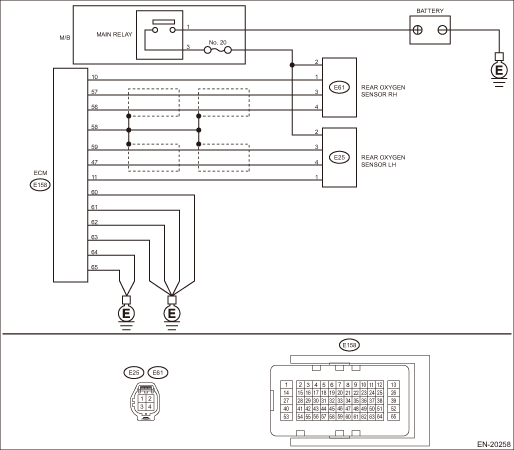
DTC DETECTING CONDITION: Detected when two consecutive driving cycles with fault occur. CAUTION: After servicing or replacing faulty parts, perform Clear Memory Mode Clear Memory Mode > OPERATION, and Inspection Mode Inspection Mode > PROCEDURE. WIRING DIAGRAM: • Engine Electrical System ENGINE TYPE EZ (WITHOUT PUSH BUTTON START) Engine Electrical System > WIRING DIAGRAM • Engine Electrical System ENGINE TYPE EZ (WITH PUSH BUTTON START) Engine Electrical System > WIRING DIAGRAM
1. OUTLINE OF DIAGNOSIS NOTE: For the detection standard, refer to DTC P0038. Diagnostic Procedure with Diagnostic Trouble Code (DTC) > DTC P0038 A/F / O2 HEATER CONTROL CIRCUIT HIGH BANK 1 SENSOR 2 |
 Dtc p013c o2 sensor slow response - rich to lean bank 2 sensor 2
DTC DETECTING CONDITION:Detected when two consecutive driving cycles with fault occur.CAUTION:After servicing or replacing faulty parts, perform Clear Memory Mode Clear Memory Mode > OPERATION, and I ...
 Dtc p0057 a/f / o2 heater control circuit low bank 2 sensor 2
DTC DETECTING CONDITION:Detected when two consecutive driving cycles with fault occur.CAUTION:After servicing or replacing faulty parts, perform Clear Memory Mode Clear Memory Mode > OPERATION, and I ...
Other materials:
Bulkhead wiring harness (in engine compartment) rh location
ConnectorConnecting toNo.PoleColorAreaNo.DescriptionAB162YB-1 Front sub sensor RHB35BB-2 Mass air flow & intake air temperature sensorB62GrB-3 Front ABS wheel speed sensor RHB1116GrB-4T14Transmission cordB125GrB-4T3Inhibitor switch (engine type FB)12GrB-4T3Inhibitor switch (engine type EZ)B2220GrB-4 ...
