Subaru Legacy BN/BS (2015-2019) Service Manual: Removal
1. Fully open the front hood. NOTE 2. Remove the collector cover. (1) Carefully pull up the rear of collector cover at two positions (A). (2) Carefully pull up the front of collector cover at two positions (B) while moving it forward.
3. Collect the refrigerant. Refrigerant Recovery Procedure > PROCEDURE 4. Release the fuel pressure. Fuel > PROCEDURE 5. Open the fuel filler lid and remove the fuel filler cap. NOTE: This operation is required to release the inner pressure of the fuel tank. 6. Disconnect the ground terminal from battery sensor. NOTE 7. Remove the air intake duct. Air Intake Duct > REMOVAL 8. Remove the air intake boot. Air Intake Boot > REMOVAL 9. Remove the air cleaner case (rear) together with the air cleaner element. Air Cleaner Case > REMOVAL 10. Remove the radiator. Radiator > REMOVAL 11. Disconnect the connector (A) and terminal (B) from the generator. 12. Disconnect the connector (C) and connector (D) from the A/C compressor. 13. Remove the harness cover (E) from the collector cover bracket. 14. Remove the clip (F) from the fuel pipe protector (LH), and move the generator cord to the left side wheel apron.
15. Disconnect the A/C pressure hoses from A/C compressor. Hose and Pipe > REMOVAL 16. Disconnect the brake booster vacuum hose.
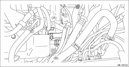
17. Disconnect the heater inlet hose (A) and the heater outlet hose (B).
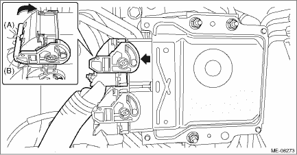
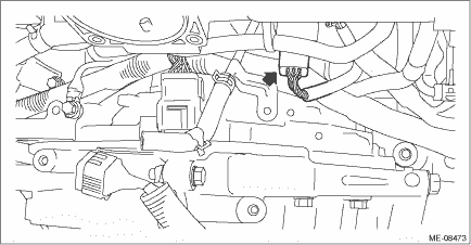
18. Disconnect the engine harness connector (A) from the main fuse box, and remove the engine harness from the claw (B) of the main fuse box. 19. Remove the engine harness from the clip (C) and move the engine harness to the engine side.
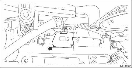
20. While pressing the area (A) shown in the figure, move the lock lever (B) in the direction of the arrow to disconnect the engine harness connector from ECM.
21. Lift up the vehicle. 22. Remove the front exhaust pipe. Front Exhaust Pipe > REMOVAL 23. Disconnect the ground cable on the engine side.
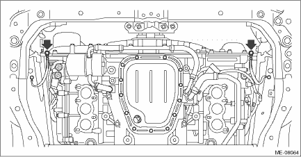
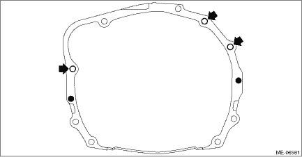
24. Remove the bolts and nuts which hold the lower side of transmission to the engine.
25. Lower the vehicle. 26. Remove the starter. Starter > REMOVAL 27. Separate the torque converter clutch from the drive plate. (1) Remove the service hole plug.
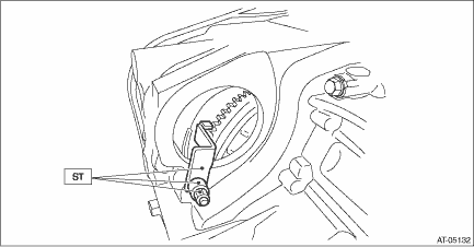
(2) Insert the wrench into the crank pulley bolt, and rotate the crank pulley to remove the four bolts securing the torque converter clutch to the drive plate. (3) Attach the ST to the torque converter clutch case.
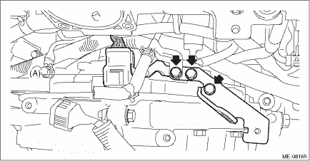
28. Disconnect the fuel delivery tube and evaporation hose. CAUTION: • Be careful not to spill fuel. • Catch the fuel from the tubes using a container or cloth. (1) Remove the clip (A) securing the fuel delivery tube. (2) Attach ST to the fuel pipe assembly and push ST in the direction of arrow mark to disconnect the quick connector of the fuel delivery tube (B).
(3) Disconnect the evaporation hose (C) from the fuel pipe assembly.
29. Remove the throttle body. Throttle Body > REMOVAL 30. Disconnect the sensor harness connector.
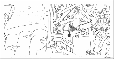
31. Remove the engine harness connector (A) from the engine hanger bracket, and remove the engine hanger bracket.
32. Remove the collector cover bracket from the intake manifold.
33. Disconnect the engine harness connector. NOTE: This procedure is required to prevent the ST from contacting with the connectors in the next step.
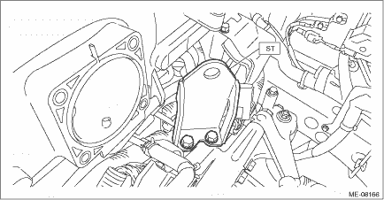
34. Attach the ST.
Tightening torque: 19 N·m (1.9 kgf-m, 14.0 ft-lb)
35. Support the engine with a lifting device and wire ropes.
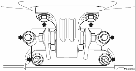
36. Remove the bolts and nuts securing the front mounting bracket to the cradle and the bracket, and remove the front cushion rubber together with the front mounting bracket from the chain cover.
37. Remove the bolt securing the upper side of the transmission to the engine, and separate the transmission and the engine. CAUTION: Before removing the engine away from transmission, check to be sure no work has been overlooked.
38. Remove the engine from the vehicle. NOTE: Be careful not to damage adjacent parts or body panels with crank pulley, oil level gauge, etc. (1) Move the engine horizontally until engine is withdrawn from transmission. (2) Slowly move the engine away from engine compartment. |


 Engine assembly
...
 Inspection
1. Check that the pipes, hoses, connectors and clips are securely connected.2. Check the engine coolant is at specified level.3. Check CVTF is at the specified level.4. Start the engine and check for ...
Other materials:
Inspection
1. CAMSHAFT POSITION SENSOR1. Disconnect the ground terminal from battery sensor. NOTE2. Prepare an oscilloscope.3. While pressing the section (A) shown in the figure, move the lock lever (B) in the direction of the arrow to disconnect the connectors from the ECM in numerical order as shown in the ...
