Subaru Legacy BN/BS (2015-2019) Service Manual: Assembly
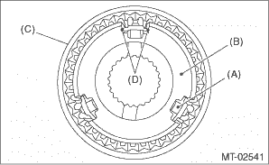
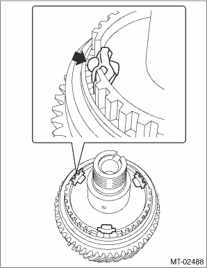
NOTE: • Match the alignment marks, and install the coupling sleeve and then install the shifting insert. • Make sure that there is no large clearance at both sides of the shifting insert after assembly.
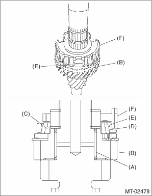
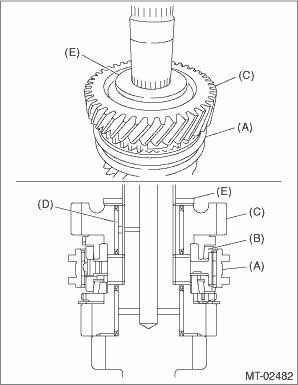
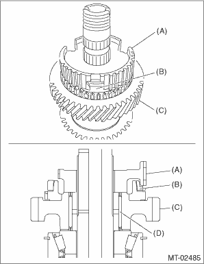
1. Install the 3rd needle bearing, 3rd drive gear, 3rd outer baulk ring, 3rd synchro cone, 3rd inner baulk ring and 3rd-4th synchronizer hub. NOTE: • Install the 3rd-4th synchronizer hub in the correct direction. • Align the protrusion of the 3rd outer baulk ring into the groove of the 3rd-4th synchronizer hub.
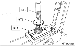
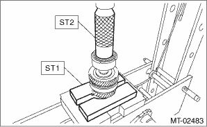
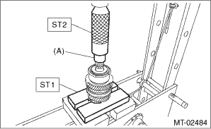
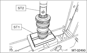
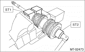
2. Install the 4th needle bearing race using ST1, ST2, ST3 and a press. CAUTION: Do not apply a load in excess of 10 kN (1 ton, 1.1 US ton, 1.0 Imp ton).
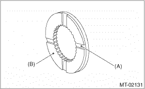
3. Install the 3rd-4th coupling sleeve. NOTE: • Install the 3rd-4th coupling sleeve in the correct direction. • Align the alignment marks of 3rd-4th coupling sleeve and the 3rd-4th synchronizer hub.
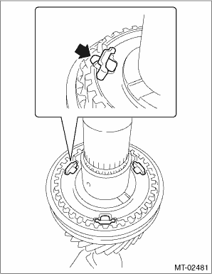
4. Install the 3rd-4th shifting insert. NOTE: Press in the ball part to install.
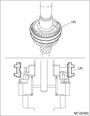
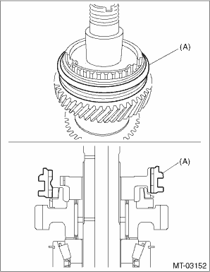
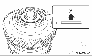
5. Install the 4th baulk ring, 4th needle bearing, 4th drive gear and 4th gear thrust washer. NOTE: • Align the protrusion of the 4th baulk ring into the groove of the 3rd-4th synchronizer hub. • Install the 4th gear thrust washer with the groove side facing the 4th drive gear.
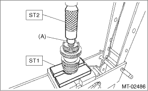
6. Install the double taper roller bearing using ST1, ST2 and a press. CAUTION: Do not apply a load in excess of 10 kN (1 ton, 1.1 US ton, 1.0 Imp ton). NOTE: • Use a new double taper roller bearing. • Install the double taper roller bearing with snap ring side facing the 5th drive gear side.
7. Make sure that the double taper roller bearing turns smoothly. 8. Install the 5th needle bearing race using ST1, ST2 and press. CAUTION: Do not apply a load in excess of 10 kN (1 ton, 1.1 US ton, 1.0 Imp ton).
9. Install the 5th needle bearing, 5th drive gear, 5th baulk ring, and 5th-6th synchronizer hub. NOTE: • Align the protrusion part of the 5th baulk ring with the groove of the 5th-6th synchronizer hub. • Install the 5th-6th synchronizer hub in the correct direction.
10. Install the 6th needle bearing race using ST1, ST2 and press. CAUTION: Do not apply a load in excess of 10 kN (1 ton, 1.1 US ton, 1.0 Imp ton).
11. Install the 5th-6th coupling sleeve. NOTE: • Install the 5th-6th coupling sleeve in the correct direction. • Align the alignment marks of 5th-6th coupling sleeve and the 5th-6th synchronizer hub.
12. Install the 5th-6th shifting insert. NOTE: Press in the ball part to install.
13. Install the 6th baulk ring, 6th drive gear and 6th needle bearing.
14. Install the ball bearing using ST2 and a press. CAUTION: Do not apply a load in excess of 10 kN (1 ton, 1.1 US ton, 1.0 Imp ton). NOTE: Install the ball bearing with the side which does not have lock nut mounting dent facing 6th drive gear.
15. Install the lock washer. NOTE: • Use a new lock washer. • Install the lock washer in the correct direction.
16. Install the lock nut using ST1 and ST2. NOTE: Use a new lock nut. Tightening torque: 160 N·m (16.3 kgf-m, 118.0 ft-lb)
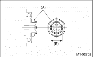
17. Crimp the lock nut at two locations so that the dimension (B) becomes 23.3 mm (0.92 in) or less. CAUTION: When crimping the lock nut, be careful not to crack it.
|
 Disassembly
NOTE:When replacing the coupling sleeve and synchronizer hub, replace them as a set. Because these must engage at the specified point, avoid disassembly as much as possible. If it is necessary to disa ...

Other materials:
Airbag warning light illumination pattern inspection
Turn the ignition switch to ON, and confirm that the airbag warning light remains on for approx. 6 seconds then turns off afterwards.(1)Airbag warning light(2)Approx. 6 seconds(3)Ignition switch ON ...
