Subaru Legacy BN/BS (2015-2019) Service Manual: Disassembly
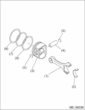
NOTE: To prevent confusion of various parts, mark each part. 1. Remove the connecting rod bearing. 2. Remove the piston rings using piston ring expander. 3. Remove the oil ring by hand. NOTE: Arrange the removed piston rings in proper order, to prevent confusion. 4. Remove the circlip on one end from the piston using a flat tip screwdriver. NOTE: Be careful not damage the piston, by wrapping the tip of flat tip screwdriver with tape. 5. Remove the piston pin from the piston. 6. Separate the piston and connecting rod. NOTE: Mark the direction of front side to each connecting rod. 7. Remove the circlip on other end from the piston using a flat tip screwdriver. NOTE: Be careful not damage the piston, by wrapping the tip of flat tip screwdriver with tape. 8. Remove the plug and orifice from the cylinder block as necessary. General Description > COMPONENT |
 Inspection
1. CYLINDER BLOCK1. Visually check for cracks or damage. Use liquid penetrant tester on the important sections for checking. Check that there are no marks of gas leaking or water leaking on gasket ins ...
 Cylinder head
...
Other materials:
Electrical specification
NOTE:The terminal numbers of the power steering control module connectors are as indicated in the figure.ContentConnector No.Terminal No.Input/output signalMeasured value and measuring conditionsPower supply (IG SW)B4505Battery voltage is detected with the ignition switch ON when measuring between ( ...
