Subaru Legacy BN/BS (2015-2019) Service Manual: Inspection
Repair or replace the differential gear in the following cases: • When the hypoid driven gear and drive pinion shaft tooth surfaces are damaged, excessively worn, or seized. • When the roller bearing on the drive pinion shaft has a worn or damaged roller path. • When there is damage, wear or seizure of the differential bevel pinion, differential bevel gear, adjusting washer, pinion shaft or straight pin. • When the differential case sliding surfaces are worn or damaged.
1. DIFFERENTIAL BEVEL PINION GEAR BACKLASH Measure the backlash between the differential bevel gear and differential bevel pinion. Adjust the backlash if not within specified limit. Front Differential Assembly > ADJUSTMENT Standard backlash 0.13 — 0.18 mm (0.0051 — 0.0071 in)
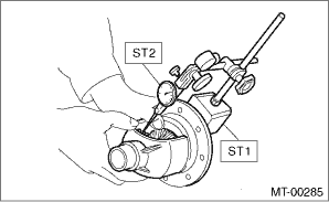
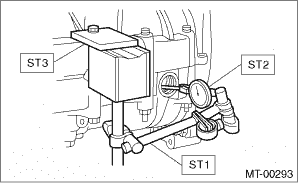
2. HYPOID DRIVEN GEAR BACKLASH 1. Set the ST1, ST2 and ST3. Insert the dial gauge probe through drain plug hole so that the probe comes in contact with the tooth surface on the right corner, and check the backlash.
2. Install SUBARU genuine axle shafts to both sides, rotate in the inversion direction so that the gauge contacts the tooth surface, and read the dial gauge. NOTE: If the backlash is outside the specified range, adjust it by turning the differential side retainers on the left and right side. Backlash 0.13 — 0.18 mm (0.0051 — 0.0071 in)
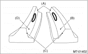
3. TOOTH CONTACT OF HYPOID DRIVEN GEAR Check tooth contact of hypoid driven gear as follows: Apply a thin uniform coat of red lead on both teeth surfaces on 3 or 4 teeth of the hypoid gear. Move the hypoid driven gear back and forth by turning the transmission main shaft until a definite contact pattern is developed on the hypoid driven gear, and judge whether face contact is correct. When the contact pattern is not correct, adjust. Front Differential Assembly > ADJUSTMENT • Tooth contact is correct.
|
 Installation
1. Install the differential side retainers using ST.ST 18630AA010WRENCH COMPL RETAINER2. Install the taper roller bearing outer race to the transmission case.3. Install the front differential assem ...
 Disassembly
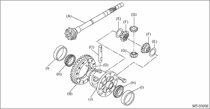
1. DIFFERENTIAL CASE ASSEMBLY1. Loosen the twelve bolts and remove hypoid driven gear.(A)Hypoid driven gear2. Drive out the straight pin from differential assembly toward hypoid driven gear side.ST ...
Other materials:
Read cancel code operation
1. On «Start» display, select «Diagnosis».2. On «Vehicle selection» display, input the target vehicle information and select «Confirmed».3. On «Main Menu» display, select «Each System».4. On «Select System» display, select «Engine Control System».5. Drive vehicle at 40 km/h (25 MPH) ...
