Subaru Legacy BN/BS (2015-2019) Service Manual: Installation
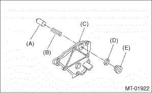
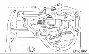
1. Clean the mating surface of the transmission cover and transfer case. 2. Install the shift accent plunger and the check ball spring. NOTE: Use new seal rings. Tightening torque: 25 N·m (2.5 kgf-m, 18.4 ft-lb)
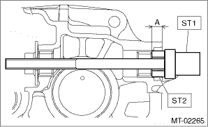
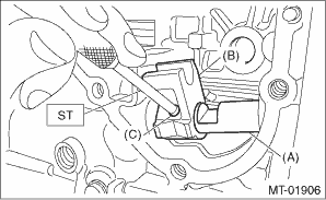
3. Using the ST, install the needle bearing. NOTE: • Use a new needle bearing. • If the press-fit depth exceeds the service limit, replace with a new needle bearing.
Press-fit depth of needle bearing: A: 8.5±0.2 mm (0.33±0.01 in) from the end of transfer case
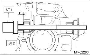
B: 0.2±0.2 mm (0.01±0.01 in) from the end of transfer case
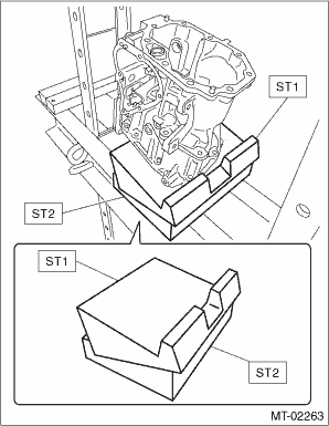
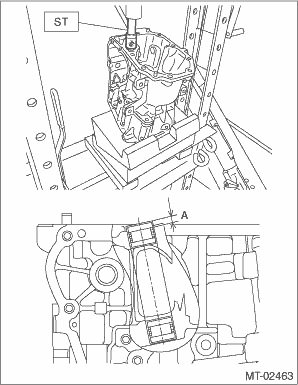
4. Set ST1, ST2 and transfer case to a press. NOTE: • Set the ST2 under ST1. • Set the transfer case so that the hole for shifter arm is positioned vertically.
5. Using the ST, install the roller bearing. NOTE: • Use a new roller bearing. • Gradually perform the press-fit operation while measuring the press-fit depth. • If the press-fit depth exceeds the service limit, replace with a new bearing.
Press-fit depth of roller bearing: A: 5.1±0.2 mm (0.20±0.01 in) from the finished surface of transfer case
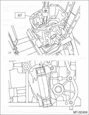
6. Flip over the transfer case, and set an iron plate between transfer case and ST. NOTE: • Insert the iron plate which is thicker than the exposed length of the transfer case knock pin between the ST and transfer case. • Set the parts while taking care that the transfer case knock pin and the roller bearing do not ride over the iron plate. 7. Using the ST, install the roller bearing. NOTE: • Use a new roller bearing. • Gradually perform the press-fit operation while measuring the press-fit depth. • If the press-fit depth exceeds the service limit, replace with a new bearing.
Press-fit depth of roller bearing: A: 0±0.2 mm (0±0.01 in) from the end of transfer case
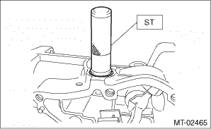
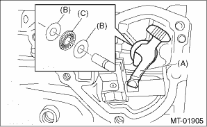
8. Using the ST, install the oil seal. NOTE: • Use a new oil seal. • The illustration shows the oil seal of selector lever COMPL. Perform the same procedures for installing the oil seal of shifter arm No. 2. • Apply transmission gear oil to the oil seal lips.
Press-fit depth of oil seal: 1±0.2 mm (0.04±0.01 in) from the end of transfer case
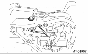
9. Insert the shifter arm and fix with a straight pin. NOTE: Use a new straight pin.
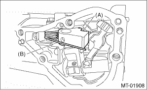
10. Install the shifter arm No. 2, adjusting washers and thrust bearing. CAUTION: Be careful not to damage the oil seal.
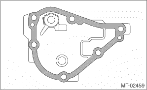
11. Install the shifter arm collar and neutral set spring. NOTE: Use a new gasket. Tightening torque: 6.4 N·m (0.7 kgf-m, 4.7 ft-lb)
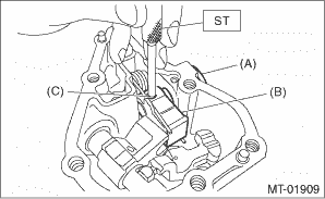
12. Install the selector arm No. 2.
13. Insert the selector lever COMPL and fix with a straight pin. CAUTION: Be careful not to damage the oil seal. NOTE: Use a new straight pin.
14. Insert a new straight pin.
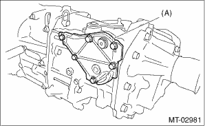
15. Install the center differential and transfer driven gear as a unit. 16. Install the transfer case and the extension case assembly. Transfer Case and Extension Case Assembly > INSTALLATION 17. Apply liquid gasket seamlessly. Liquid gasket: THREE BOND 1215B or equivalent
18. Install the transmission cover. Tightening torque: 25 N·m (2.5 kgf-m, 18.4 ft-lb)
19. Install the back-up light switch and the neutral position switch. Switches and Harness > INSTALLATION 20. Install the manual transmission assembly to the vehicle. Manual Transmission Assembly > INSTALLATION |
 Removal
1. Remove the manual transmission assembly from the vehicle. Manual Transmission Assembly > REMOVAL2. Remove the back-up light switch and the neutral position switch. Switches and Harness > REMOVAL3 ...

Other materials:
Inspection
SymptomsInspection stepsHorn does not sound1. Check the fuse.2. Check the horn relay.3. Check the roll connector.4. Check the horn switch.5. Check the horn assembly.6. Check the harness. ...
