Subaru Legacy BN/BS (2015-2019) Service Manual: Adjustment
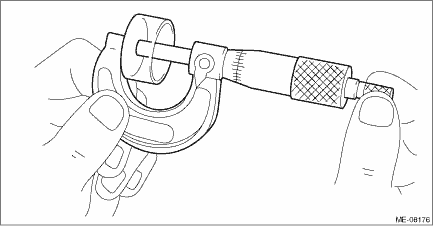
1. INTAKE SIDE 1. Remove the engine from the vehicle. Engine Assembly > REMOVAL 2. Measure all the valve clearances. Valve Clearance > INSPECTION NOTE: Record each valve clearance after measurement. 3. Remove the timing chain assembly. Timing Chain Assembly > REMOVAL 4. Remove the cam sprocket. Cam Sprocket > REMOVAL 5. Remove the camshaft. Camshaft > REMOVAL 6. Remove the valve lifter. 7. Measure the thickness of valve lifter using micrometer.
8. Select a valve lifter of suitable thickness using the measured valve clearance and valve lifter thickness, and install it. NOTE: Use a new valve lifter.
9. Install the camshaft. Camshaft > INSTALLATION 10. Install the cam sprocket. Cam Sprocket > INSTALLATION 11. Install the timing chain assembly. Timing Chain Assembly > INSTALLATION 12. Measure all valve clearance again at this time. If the valve clearance is not within the adjustment value, repeat the procedure from step 3). Valve clearance (adjustment value): 0.20+0.04 −0.06 mm (0.0079+0.0016 −0.0024 in) 13. After adjustment, install the related parts in the reverse order of removal. NOTE: Refer to “Camshaft” when installing the rocker cover. Camshaft > INSTALLATION 2. EXHAUST SIDE 1. Remove the engine from the vehicle. Engine Assembly > REMOVAL 2. Measure all the valve clearances. Valve Clearance > INSPECTION NOTE: Record each valve clearance after measurement. 3. Remove the camshaft. Camshaft > REMOVAL 4. Remove the valve lifter. 5. Measure the thickness of valve lifter using micrometer.
6. Select a valve lifter of suitable thickness using the measured valve clearance and valve lifter thickness, and install it. NOTE: Use a new valve lifter.
7. Install the camshaft. Camshaft > INSTALLATION 8. Install the cam sprocket. Cam Sprocket > INSTALLATION 9. Install the timing chain assembly. Timing Chain Assembly > INSTALLATION 10. Measure all valve clearance again at this time. If the valve clearance is not within the adjustment value, repeat the procedure from step 3). Valve clearance (adjustment value): 0.35±0.05 mm (0.0138±0.0020 in) 11. After adjustment, install the related parts in the reverse order of removal. NOTE: Refer to “Camshaft” when installing the rocker cover. Camshaft > INSTALLATION |
 Inspection
CAUTION:If engine oil is spilt onto the exhaust pipe, wipe it off with cloth to avoid emission of smoke or causing a fire.NOTE:Inspection of valve clearance should be performed while engine is cold.1. ...
 V-belt
...
Other materials:
3.6 L models
1) Clips
Unsnap the two clips holding the air
cleaner case (rear).
Open the air cleaner case and remove
the air cleaner element.
CAUTION
If the inside of the air cleaner case is
extremely soiled (for example, by
sand), contact a SUBARU dealer
and have the ...
