Subaru Legacy BN/BS (2015-2019) Service Manual: Disassembly
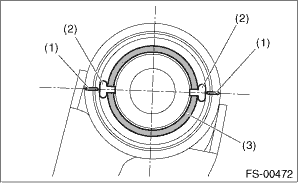
1. BUSHING FRONT - FRONT ARM 1. Put an alignment mark on the front arm assembly based on the split portion of the bushing intermediate plate of the busing front - front arm. CAUTION: Always put an alignment mark for aligning the position on bushing installation.
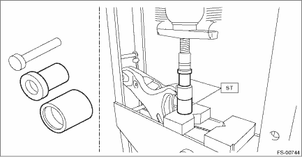
2. Using the ST and a press, remove the front bushing. Preparation tool: ST: INSTALLER & REMOVER SET (927680000)
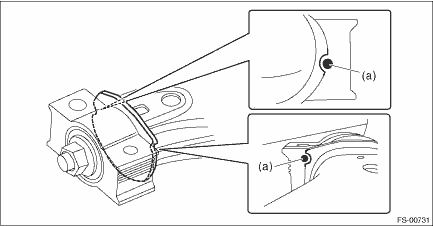
2. BUSHING REAR - FRONT ARM 1. Remove the rear bushing assembly. (1) Put alignment marks on the front arm assembly and the bushing rear - front arm. • Front arm assembly replacement: put an alignment mark (a) from the cutout portion of the front arm assembly to the bushing rear - front arm.
• Bushing rear - front arm replacement: put an alignment mark (b) on the front arm assembly located on an imaginary line extending from the rib portion of the bushing rear - front arm.
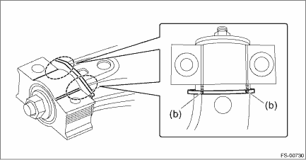
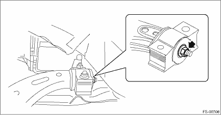
(2) Remove the self-locking nut, and then remove the rear bushing assembly.
|
 Installation
1. Before installation, inspect the following items and replace any faulty part with a new one.• Check the front arm for damage or cracks, and replace if defective.• Visually check the bus ...
 Front ball joint
...
Other materials:
Dtc p0420 catalyst system efficiency below threshold bank 1
DTC DETECTING CONDITION:Detected when two consecutive driving cycles with fault occur.TROUBLE SYMPTOM:• Engine stalls.• Idle mixture is out of specifications.CAUTION:After servicing or replacing faulty parts, perform Clear Memory Mode Clear Memory Mode > OPERATION, and Inspection Mode ...
