1.CHECK LAN SYSTEM. Inspect LAN system. Basic Diagnostic Procedure > PROCEDURE | | Diagnostic Procedure with Diagnostic Trouble Code (DTC) > DTC B2271 IGN RELAY CONTROL CIRCUIT | Perform the inspection according to the diagnosis for LAN system. |
2.CHECK FUSE. Check the fuse. Relay and Fuse > INSPECTION | | Diagnostic Procedure with Diagnostic Trouble Code (DTC) > DTC B2271 IGN RELAY CONTROL CIRCUIT | Replace the fuse. When the replaced fuse is blown immediately, check the power supply circuit for short-circuited. |
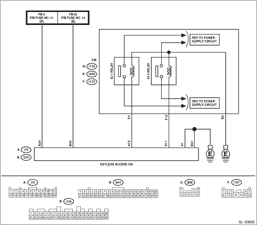
3.CHECK HARNESS. 1) Disconnect the keyless access CM connector. 2) Using a tester, measure the voltage between the keyless access CM connector and chassis ground. Connector & terminal (i75) No. 24 (+) — Chassis ground (−): (i241) No. 40 (+) — Chassis ground (−): | Is the voltage 9.5 — 16 V- | Diagnostic Procedure with Diagnostic Trouble Code (DTC) > DTC B2271 IGN RELAY CONTROL CIRCUIT | Check the power supply circuit. |
4.CHECK HARNESS. Using a tester, measure the resistance between the keyless access CM connector and chassis ground. Connector & terminal (i241) No. 21 — Chassis ground: (i75) No. 1 — Chassis ground: | Is the resistance less than 1 -- | Diagnostic Procedure with Diagnostic Trouble Code (DTC) > DTC B2271 IGN RELAY CONTROL CIRCUIT | Repair or replace the open circuit of harness. |
5.CHECK HARNESS. 1) Disconnect the keyless access CM connector. 2) Using a tester, measure the resistance between the keyless access CM connector and chassis ground. Connector & terminal (i75) No. 11 — Chassis ground: | Is resistance 74.15 — 460.88 -- (20°C) | Diagnostic Procedure with Diagnostic Trouble Code (DTC) > DTC B2271 IGN RELAY CONTROL CIRCUIT | Check IG relay 2. Diagnostic Procedure with Diagnostic Trouble Code (DTC) > DTC B2271 IGN RELAY CONTROL CIRCUIT |
6.CHECK HARNESS. 1) Disconnect the keyless access CM connector. 2) Using a tester, measure the resistance between the keyless access CM connector and chassis ground. Connector & terminal (i75) No. 12 — Chassis ground: | Is resistance 50.87 — 72.17 -- (20°C) | Diagnostic Procedure with Diagnostic Trouble Code (DTC) > DTC B2271 IGN RELAY CONTROL CIRCUIT | Check IG relay 1. Diagnostic Procedure with Diagnostic Trouble Code (DTC) > DTC B2271 IGN RELAY CONTROL CIRCUIT |
7.CHECK RELAY. Perform unit inspection of IG relay 1 and IG relay 2. Relay and Fuse > INSPECTION | | Diagnostic Procedure with Diagnostic Trouble Code (DTC) > DTC B2271 IGN RELAY CONTROL CIRCUIT | Replace the relay. Relay and Fuse |
8.CHECK KEYLESS ACCESS CM. 1) Connect the keyless access CM connector. 2) Using a tester, measure the voltage between the terminals of keyless access CM connector. Connector & terminal (i75) No. 11 (+) — Chassis ground (−): (i75) No. 12 (+) — Chassis ground (−): | Is the voltage 1 V or less > 9.5 — 16 V when ACC > IGN ON- | Even if DTC is displayed, the circuit has returned to a normal condition at this time. Reproduce the failure, and then perform the diagnosis again. NOTE: In this case, temporary poor contact of connector, temporary open or short circuit of harness may be the cause. | Replace the keyless access CM. Keyless Access CM > REMOVAL |
 Dtc b2274 acc relay control circuit
 Dtc u0101 lost communication with tcm