Honda Civic manuals

Subaru Legacy BN/BS (2015-2019) Service Manual: Dtc p0010 "a" camshaft position actuator control circuit/open bank 1

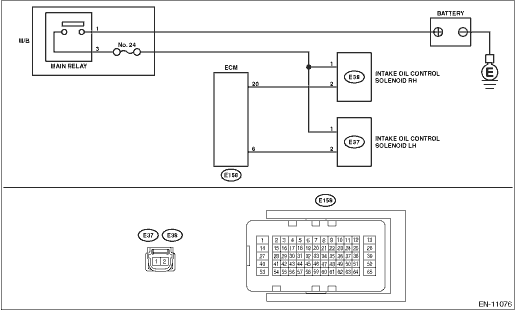
DTC DETECTING CONDITION:

Immediately at fault recognition

TROUBLE SYMPTOM:

Improper idling

CAUTION:

After servicing or replacing faulty parts, perform Clear Memory Mode Clear Memory Mode > OPERATION, and Inspection Mode Inspection Mode > PROCEDURE.

WIRING DIAGRAM:

Engine Electrical System ENGINE TYPE FB (WITHOUT PUSH BUTTON START) Engine Electrical System > WIRING DIAGRAM

Engine Electrical System ENGINE TYPE FB (WITH PUSH BUTTON START) Engine Electrical System > WIRING DIAGRAM

STEPCHECKYESNO

1.CHECK OUTPUT SIGNAL OF ECM.

1) Turn the ignition switch to ON.

2) Measure the voltage between ECM connector and chassis ground.

Connector & terminal

(E158) No. 20 (+) — Chassis ground (−):

Is the voltage 10 V or more-

Diagnostic Procedure with Diagnostic Trouble Code (DTC) > DTC P0010 "A" CAMSHAFT POSITION ACTUATOR CONTROL CIRCUIT/OPEN BANK 1

Diagnostic Procedure with Diagnostic Trouble Code (DTC) > DTC P0010 "A" CAMSHAFT POSITION ACTUATOR CONTROL CIRCUIT/OPEN BANK 1

2.CHECK FOR POOR CONTACT.

Check for poor contact of ECM connector.

Is there poor contact of ECM connector-

Repair the poor contact of ECM connector.

Even if DTC is detected, the circuit has returned to a normal condition at this time. Reproduce the failure, and then perform the diagnosis again.

NOTE:

In this case, temporary poor contact of connector, temporary open or short circuit of harness may be the cause.

3.CHECK POWER SUPPLY TO THE INTAKE OIL CONTROL SOLENOID RH.

Measure the voltage between intake oil control solenoid RH connector and engine ground.

Connector & terminal

(E38) No. 1 (+) — Engine ground (−):

Is the voltage 10 V or more-

Diagnostic Procedure with Diagnostic Trouble Code (DTC) > DTC P0010 "A" CAMSHAFT POSITION ACTUATOR CONTROL CIRCUIT/OPEN BANK 1

Repair the power supply circuit.

4.CHECK HARNESS BETWEEN ECM AND INTAKE OIL CONTROL SOLENOID RH CONNECTOR.

1) Turn the ignition switch to OFF.

2) Disconnect the connectors from the ECM and intake oil control solenoid RH.

3) Measure the resistance between intake oil control solenoid RH connector and engine ground.

Connector & terminal

(E38) No. 2 — Engine ground:

Is the resistance 1 M- or more-

Diagnostic Procedure with Diagnostic Trouble Code (DTC) > DTC P0010 "A" CAMSHAFT POSITION ACTUATOR CONTROL CIRCUIT/OPEN BANK 1

Repair the short circuit to ground in harness between ECM connector and intake oil control solenoid RH connector.

5.CHECK HARNESS BETWEEN ECM AND INTAKE OIL CONTROL SOLENOID RH CONNECTOR.

Measure the resistance of harness between ECM connector and intake oil control solenoid RH.

Connector & terminal

(E158) No. 20 — (E38) No. 2:

Is the resistance less than 1 --

Diagnostic Procedure with Diagnostic Trouble Code (DTC) > DTC P0010 "A" CAMSHAFT POSITION ACTUATOR CONTROL CIRCUIT/OPEN BANK 1

Repair the open circuit in harness between ECM connector and intake oil control solenoid RH connector.

6.CHECK INTAKE OIL CONTROL SOLENOID RH.

Measure the resistance between intake oil control solenoid RH terminals.

Terminals

No. 1 — No. 2:

Is the resistance 6 — 12 --

Repair the poor contact of intake oil control solenoid RH connector.

Replace the intake oil control solenoid RH. Oil Control Solenoid

1. OUTLINE OF DIAGNOSIS

Detect open or short circuit of the oil control solenoid.

Judge as NG when the current is small even though the duty signal is large.

2. EXECUTION CONDITION

Secondary Parameters

Execution condition

Battery voltage

≥ 10.9 V

Oil control solenoid control duty

≥ 99.61 %

3. GENERAL DRIVING CYCLE

Always perform the diagnosis continuously.

4. DIAGNOSTIC METHOD

If the duration of time while the following conditions are met is longer than the time indicated, judge as NG.

Judgment Value

Malfunction Criteria

Threshold Value

Oil control solenoid control present current

< 0.306 A

Time Needed for Diagnosis: 2000 ms

Malfunction Indicator Light Illumination: Illuminates as soon as a malfunction occurs.

Dtc p0011 "a" camshaft position - timing over-advanced or system performance bank 1
DTC DETECTING CONDITION:Detected when two consecutive driving cycles with fault occur.TROUBLE SYMPTOM:• Engine stalls.• Improper idlingCAUTION:After servicing or replacing faulty parts, pe ...

Dtc p000c "a" camshaft position slow response bank 2
NOTE:For the diagnostic procedure, refer to DTC P0021. Diagnostic Procedure with Diagnostic Trouble Code (DTC) > DTC P0021 "A" CAMSHAFT POSITION - TIMING OVER-ADVANCED OR SYSTEM PERFORMANCE BANK 21. ...

Other materials:

Assembly
1. Install the valve spring and valve.(1) Set the cylinder head on ST.ST 18250AA010CYLINDER HEAD TABLE(2) Coat the stem of each valve with engine oil and insert the valve into valve guide.NOTE:When inserting the valve into valve guide, use special care not to damage the oil seal lip.(3) Install t ...

© 2017-2024 Copyright www.sulegacy.com