Subaru Legacy BN/BS (2015-2019) Service Manual: Dtc p0038 a/f / o2 heater control circuit high bank 1 sensor 2
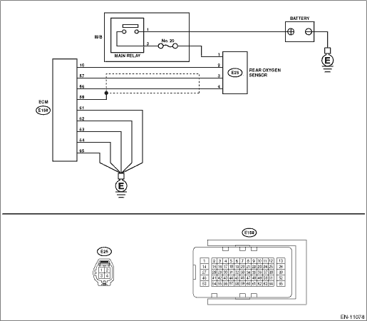
DTC DETECTING CONDITION: Detected when two consecutive driving cycles with fault occur. CAUTION: After servicing or replacing faulty parts, perform Clear Memory Mode Clear Memory Mode > OPERATION, and Inspection Mode Inspection Mode > PROCEDURE. WIRING DIAGRAM: • Engine Electrical System ENGINE TYPE FB (WITHOUT PUSH BUTTON START) Engine Electrical System > WIRING DIAGRAM • Engine Electrical System ENGINE TYPE FB (WITH PUSH BUTTON START) Engine Electrical System > WIRING DIAGRAM
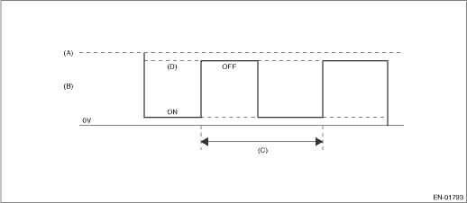
1. OUTLINE OF DIAGNOSIS Detect the rear oxygen sensor heater open or short circuit. The rear oxygen sensor heater performs duty control, and the output terminal voltage at ON is 0 V, and the output terminal voltage at OFF is the battery voltage. Judge as NG when the terminal voltage remains High. 2. COMPONENT DESCRIPTION
3. EXECUTION CONDITION
4. GENERAL DRIVING CYCLE Perform the diagnosis continuously after the enable conditions have been established. 5. DIAGNOSTIC METHOD If the duration of time while the following conditions are met is longer than the time indicated, judge as NG.
Time Needed for Diagnosis: 2.56 seconds Malfunction Indicator Light Illumination: Illuminates when malfunction occurs in 2 continuous driving cycles. |
 Dtc p0068 map/maf - throttle position correlation
DTC DETECTING CONDITION:Detected when two consecutive driving cycles with fault occur.CAUTION:After servicing or replacing faulty parts, perform Clear Memory Mode Clear Memory Mode > OPERATION, and I ...
 Dtc p0037 a/f / o2 heater control circuit low bank 1 sensor 2
DTC DETECTING CONDITION:Detected when two consecutive driving cycles with fault occur.CAUTION:After servicing or replacing faulty parts, perform Clear Memory Mode Clear Memory Mode > OPERATION, and I ...
Other materials:
Inspection
1. COMMUNICATION FOR INITIALIZING THE AIRBAG SYSTEM IS IMPOSSIBLEDETECTING CONDITION:Defective harness connectorTROUBLE SYMPTOM:Communication is impossible between the airbag control module and the Subaru Select Monitor.NOTE:Refer to “Communication for Initializing Impossible” in AIRBAG ...
