Honda Civic manuals

Subaru Legacy BN/BS (2015-2019) Service Manual: Dtc p0137 o2 sensor circuit low voltage bank 1 sensor 2

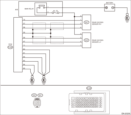
DTC DETECTING CONDITION:

Detected when two consecutive driving cycles with fault occur.

CAUTION:

After servicing or replacing faulty parts, perform Clear Memory Mode Clear Memory Mode > OPERATION, and Inspection Mode Inspection Mode > PROCEDURE.

WIRING DIAGRAM:

Engine Electrical System ENGINE TYPE EZ (WITHOUT PUSH BUTTON START) Engine Electrical System > WIRING DIAGRAM

Engine Electrical System ENGINE TYPE EZ (WITH PUSH BUTTON START) Engine Electrical System > WIRING DIAGRAM

STEPCHECKYESNO

1.CHECK REAR OXYGEN SENSOR DATA.

1) Warm up the engine until engine coolant temperature is higher than 75°C (167°F), and keep the engine speed at 3,000 rpm. (2 minutes maximum)

2) Keep the engine speed at idle. (One minute)

3) Read the value of «Front O2 Sensor #1» using the Subaru Select Monitor or a general scan tool.

NOTE:

Subaru Select Monitor

For detailed operation procedures, refer to “Read Current Data For Engine”. Subaru Select Monitor

General scan tool

For detailed operation procedures, refer to the general scan tool operation manual.

Is the value of «Front O2 Sensor #1» 0.490 V or more-

Diagnostic Procedure with Diagnostic Trouble Code (DTC) > DTC P0137 O2 SENSOR CIRCUIT LOW VOLTAGE BANK 1 SENSOR 2

Diagnostic Procedure with Diagnostic Trouble Code (DTC) > DTC P0137 O2 SENSOR CIRCUIT LOW VOLTAGE BANK 1 SENSOR 2

2.CHECK REAR OXYGEN SENSOR CONNECTOR AND COUPLING CONNECTOR.

Has water entered the connector-

Completely remove any water inside.

Diagnostic Procedure with Diagnostic Trouble Code (DTC) > DTC P0137 O2 SENSOR CIRCUIT LOW VOLTAGE BANK 1 SENSOR 2

3.CHECK HARNESS BETWEEN ECM AND REAR OXYGEN SENSOR CONNECTOR.

1) Turn the ignition switch to OFF.

2) Disconnect the connector from ECM and rear oxygen sensor.

3) Measure the resistance of harness between ECM connector and rear oxygen sensor connector.

Connector & terminal

(E158) No. 57 — (E61) No. 3:

(E158) No. 56 — (E61) No. 4:

Is the resistance less than 1 --

Diagnostic Procedure with Diagnostic Trouble Code (DTC) > DTC P0137 O2 SENSOR CIRCUIT LOW VOLTAGE BANK 1 SENSOR 2

Repair the harness and connector.

NOTE:

In this case, repair the following item:

Open circuit in harness between ECM connector and rear oxygen sensor connector

Poor contact of coupling connector

4.CHECK HARNESS BETWEEN ECM AND REAR OXYGEN SENSOR CONNECTOR.

1) Connect the connector to ECM.

2) Turn the ignition switch to ON.

3) Measure the voltage between rear oxygen sensor connector and chassis ground.

Connector & terminal

(E61) No. 3 (+) — Chassis ground (−):

Is the voltage 1.18 V or more-

Replace the rear oxygen sensor. Rear Oxygen Sensor

Repair the harness and connector.

NOTE:

In this case, repair the following item:

Open circuit in harness between ECM connector and rear oxygen sensor connector

Poor contact of ECM connector

Poor contact of coupling connector

5.CHECK EXHAUST SYSTEM.

Check exhaust system parts.

NOTE:

Check the following items.

Looseness and improper fitting of exhaust system parts

Damage (crack, hole etc.) of parts

Loose part and improper installation between front oxygen (A/F) sensor and rear oxygen sensor

Is there any fault in exhaust system-

Repair or replace faulty parts.

Replace the rear oxygen sensor. Rear Oxygen Sensor

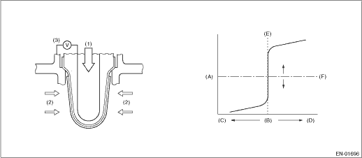
1. OUTLINE OF DIAGNOSIS

Detect for NG of the rear oxygen sensor continuity.

Judge as NG if the rear oxygen sensor voltage value is not within the range.

2. COMPONENT DESCRIPTION

(A)

Electromotive force

(B)

Air fuel ratio

(C)

Lean

(D)

Rich

(E)

Theoretical air fuel ratio

(F)

Comparative voltage

(1)

Atmosphere

(2)

Exhaust gas

(3)

Electromotive force

3. EXECUTION CONDITION

Secondary Parameters

Execution condition

Judgment 1

Battery voltage

≥ 10.9 V

Judgment 2,3

Battery voltage

≥ 10.9 V

Estimated secondary oxygen sensor element temperature

≥ 500 °C (932 °F)

Rear oxygen sensor offset voltage

≥ 1.28 V

and

> 1.68 V

Accumulated duty ratio of the rear oxygen sensor heater operation since engine started

≥ Value from Map

Map

Engine coolant temperature at engine starting

°C (°F)

−40

(−40)

−30

(−22)

−20

(−4)

−10

(14)

0

(32)

10

(50)

20

(68)

30

(86)

Accumulated duty ratio of the rear oxygen sensor heater operation since engine started

%

10500

10500

10500

10500

10500

10500

10500

10500

Engine coolant temperature at engine starting

°C (°F)

40

(104)

50

(122)

60

(140)

70

(158)

80

(176)

90

(194)

100

(212)

110

(230)

Accumulated duty ratio of the rear oxygen sensor heater operation since engine started

%

10500

10500

10500

10500

10500

10500

10500

10500

4. GENERAL DRIVING CYCLE

Perform the diagnosis continuously after the enable conditions have been established.

5. DIAGNOSTIC METHOD

If the duration of time while the following conditions are met is longer than the time indicated, judge as NG.

Judgment Value

Malfunction Criteria

Threshold Value

Judgment 1: Short to ground

Secondary oxygen sensor offset signal

< 1.28 V

Judgment 2: Circuit open

Secondary oxygen sensor signal

< 1.18 V

Judgment 3: Out of range

Secondary oxygen sensor output voltage

< −0.22 V

Time Needed for Diagnosis: 1000 ms

Malfunction Indicator Light Illumination: Illuminates when malfunction occurs in 2 continuous driving cycles.

Dtc p0138 o2 sensor circuit high voltage bank 1 sensor 2
DTC DETECTING CONDITION:Detected when two consecutive driving cycles with fault occur.CAUTION:After servicing or replacing faulty parts, perform Clear Memory Mode Clear Memory Mode > OPERATION, and I ...

Dtc p0134 a/f / o2 sensor circuit no activity detected bank 1 sensor 1
DTC DETECTING CONDITION:Immediately at fault recognitionCAUTION:After servicing or replacing faulty parts, perform Clear Memory Mode Clear Memory Mode > OPERATION, and Inspection Mode Inspection Mod ...

Other materials:

Dtc b2606 power seat position sensor circuit low
DTC DETECTING CONDITION:Short circuit in the pulse sensor is detected during the motor operation for a certain period of time (12 ms) or more.TROUBLE SYMPTOM:• Seat memory does not operate.• Seat operation stops immediately after manual operation is performed.WIRING DIAGRAM:NOTE:For the ...

© 2017-2024 Copyright www.sulegacy.com