Honda Civic manuals

Subaru Legacy BN/BS (2015-2019) Service Manual: Dtc p0455 evap system (cpc) leak detected (large leak)

DTC DETECTING CONDITION:

Detected when two consecutive driving cycles with fault occur.

TROUBLE SYMPTOM:

Fuel odor

There is a hole of more than 1.0 mm (0.04 in) dia. in evaporation system or fuel tank.

Fuel filler cap loose or lost

CAUTION:

After servicing or replacing faulty parts, perform Clear Memory Mode Clear Memory Mode > OPERATION, and Inspection Mode Inspection Mode > PROCEDURE.

STEPCHECKYESNO

1.CHECK FUEL FILLER CAP.

1) Turn the ignition switch to OFF.

2) Check the fuel filler cap.

NOTE:

The DTC is stored in memory if fuel filler cap is or was loose or if the cap chain has caught while tightening.

Is the fuel filler cap tightened securely-

Diagnostic Procedure with Diagnostic Trouble Code (DTC) > DTC P0455 EVAP SYSTEM (CPC) LEAK DETECTED (LARGE LEAK)

Tighten fuel filler cap securely.

2.CHECK FUEL FILLER CAP.

Is the fuel filler cap genuine-

Diagnostic Procedure with Diagnostic Trouble Code (DTC) > DTC P0455 EVAP SYSTEM (CPC) LEAK DETECTED (LARGE LEAK)

Replace with a genuine fuel filler cap.

3.CHECK FUEL FILLER PIPE GASKET.

Is there any damage to the seal between fuel filler cap and fuel filler pipe-

Repair or replace the fuel filler cap and fuel filler pipe. Fuel Filler Pipe

Diagnostic Procedure with Diagnostic Trouble Code (DTC) > DTC P0455 EVAP SYSTEM (CPC) LEAK DETECTED (LARGE LEAK)

4.CHECK PURGE CONTROL SOLENOID VALVE.

Check air-tightness of the purge control solenoid valve. Purge Control Solenoid Valve > INSPECTION

Is the purge control solenoid valve OK-

Diagnostic Procedure with Diagnostic Trouble Code (DTC) > DTC P0455 EVAP SYSTEM (CPC) LEAK DETECTED (LARGE LEAK)

Replace the purge control solenoid valve. Purge Control Solenoid Valve

5.CHECK EVAPORATIVE EMISSION CONTROL SYSTEM LINE.

Are there holes on the evaporation line-

Repair or replace the evaporation line. Fuel Delivery and Evaporation Lines

Diagnostic Procedure with Diagnostic Trouble Code (DTC) > DTC P0455 EVAP SYSTEM (CPC) LEAK DETECTED (LARGE LEAK)

6.CHECK CANISTER.

Are there holes on the canister-

Replace the canister. Canister

Diagnostic Procedure with Diagnostic Trouble Code (DTC) > DTC P0455 EVAP SYSTEM (CPC) LEAK DETECTED (LARGE LEAK)

7.CHECK LEAK CHECK VALVE ASSEMBLY.

Are there damage or holes on the leak check valve assembly-

Replace the leak check valve assembly. Leak Check Valve Assembly

Diagnostic Procedure with Diagnostic Trouble Code (DTC) > DTC P0455 EVAP SYSTEM (CPC) LEAK DETECTED (LARGE LEAK)

8.CHECK FUEL TANK.

Remove the fuel tank. Fuel Tank

Are there damage or holes on the fuel tank-

Repair or replace the fuel tank. Fuel Tank

Diagnostic Procedure with Diagnostic Trouble Code (DTC) > DTC P0455 EVAP SYSTEM (CPC) LEAK DETECTED (LARGE LEAK)

9.CHECK ANY OTHER MECHANICAL TROUBLE IN EVAPORATIVE EMISSION CONTROL SYSTEM.

Are there holes, cracks, clogging, or disconnection, misconnection of hoses or pipes in evaporative emission control system-

Repair or replace the hoses or pipes.

Repair the poor contact of ECM connector.

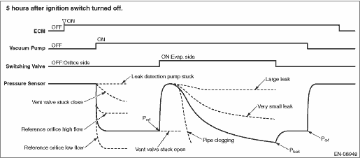
1. OUTLINE OF DIAGNOSIS

This diagnosis judges whether the ELCM operation is normal or not, and whether the evaporative emission system has leak and clogging or not.

To purge the canister, after driving, perform the five hours soaking after ignition switch OFF in order to stabilize the evaporative gas status. * After 5 or 7 or 9.5 hours passed, ECM is activated by soaking timer, and the leak check is started.

Judges whether the ELCM operation is normal or not, by measuring the reference pressure status via reference orifice (0.02 inch orifice). Judge as malfunction if the reference pressure is out of specified range. Then, judge whether there is a leak or not, by comparing the pressure (leak pressure) when the reference pressure and the evaporative emission system are in negative pressure condition. Judge as system leak in the evaporative emission system if the leak pressure is higher than reference pressure. Judge as clogging of pipe if the leak pressure becomes lower than the reference pressure within the specified amount of time.

0.02 inch leak and 0.04 inch leak can be distinguished by measuring the leak pressure.

The diagnosis results are stored inside ECM until the engine is started again.

*: When the test conditions are not met in 5 hours, perform diagnosis at elapsed time of 7 hours. When the test conditions are not met in 7 hours, perform diagnosis at elapsed time of 9.5 hours.

Diagnostic item

ELCM system (ELCM body)

Vacuum pump stuck

Switching valve stuck to open

Switching valve stuck to close

Reference orifice flow large

Reference orifice flow small

Leak check

Large leak

0.04 inch leak

Fuel cap loose

Fuel cap off

System malfunction

Very small leak

0.02 inch leak

Clogging of pipe

OUTLINE OF DIAGNOSIS

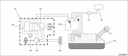
2. COMPONENT DESCRIPTION

ELCM consists of the pressure sensor, the reference orifice (diameter of 0.02 inch), the vacuum pump which introduces the negative pressure into evaporative emission system, and the switching valve which switches the passage to introduce the negative pressure.

(1)

ELCM

(5)

Vacuum pump

(9)

Fuel tank

(2)

Switching valve

(6)

Drain filter

(10)

Canister

(3)

Reference orifice (0.02 inch orifice)

(7)

Purge control solenoid valve

(4)

Pressure sensor

(8)

Intake manifold

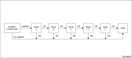
3. EXECUTION CONDITION

Secondary Parameters

Execution condition

Battery voltage

≥ 10.9 V

Barometric pressure

≥ 75.1 kPa (563 mmHg, 22.2 inHg)

Activation of soaking timer

Completed

Engine coolant temperature

≥ 4.4 °C (39.9 °F)

and

< 45 °C (113 °F)

Accumulated purge amount during previous driving cycle

≥ Value of Map 1

Map 1

Engine coolant temperature

°C (°F)

0 (32)

30 (86)

35 (95)

40 (104)

45 (113)

Accumulated purge amount during previous driving cycle

g (oz)

128 (4.51)

128 (4.51)

480 (16.93)

832 (29.34)

1184 (41.76)

4. GENERAL DRIVING CYCLE

Perform the diagnosis only once when 5 or 7 or 9.5 hours has passed after ignition switch is OFF. For more detail, refer to “OUTLINE OF DIAGNOSIS”. Diagnostic Procedure with Diagnostic Trouble Code (DTC) > DTC P0455 EVAP SYSTEM (CPC) LEAK DETECTED (LARGE LEAK)

5. DIAGNOSTIC METHOD

Mode

Explanation of Mode

Diagnosis Period

A

Vacuum pump operation confirmation and characteristics stability

7 s or less & 300 s

B

Measurement of reference pressure for setting the target negative pressure

40 s or less

C

Switching valve operation confirmation

12 s or less

D

Clogging of pipe diagnosis and leak pressure measurement

900 s or less

E

Reference pressure measurement for judgment

40 s or less

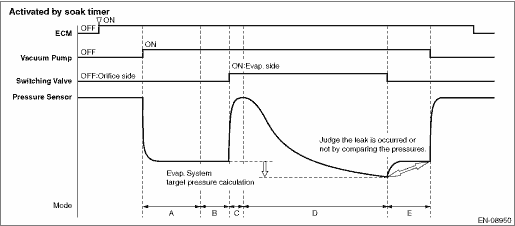
Mode A (Vacuum pump operation confirmation and characteristics stability)

Purpose: Detect the vacuum pump operation trouble.

Judge as NG when the following conditions are established.

Judge as OK if the following conditions are not established, and warm up for five minutes to stabilize the vacuum pump characteristics.

Judgment Value

Malfunction Criteria

Threshold Value

DTC

Pressure sensor output value

> −224 Pa (−1.68 mmHg, −0.1 inHg)

P2404

Mode B (Measurement of reference pressure for setting the target negative pressure)

(1) Purpose: Judge the reference pressure stability.

Judge as NG when the following conditions are established.

Judgment Value

Malfunction Criteria

Threshold Value

DTC

|Pressure sensor maximum output value − Pressure sensor minimum output value|

> 314 Pa (2.355 mmHg, 0.1 inHg)

P2404

(2) Purpose: Judge whether the reference pressure is within the normal range, and detect the vacuum pump and orifice malfunctions.

Judge as NG when the following conditions are established.

Judgment Value

Malfunction Criteria

Threshold Value

DTC

Reference pressure for setting the target negative pressure

Reference pressure for judgment

< Value of Map 2

or

> Value of Map 3

P2404

Map 2

Barometric pressure

kPa (mmHg, inHg)

70 (525, 20.7)

80 (600, 23.6)

90 (675, 26.6)

100 (750, 29.5)

Reference pressure for setting the target negative pressure

kPa (mmHg, inHg)

−4 (−29.79, −1.2)

−4.1 (−30.593, −1.2)

−4.2 (−31.395, −1.2)

−4.3 (−32.19, −1.3)

Map 3

Barometric pressure

kPa (mmHg, inHg)

70 (525, 20.7)

80 (600, 23.6)

90 (675, 26.6)

100 (750, 29.5)

Reference pressure for judgment

kPa (mmHg, inHg)

−0.9 (−7.065, −0.3)

−1 (−7.86, −0.3)

−1.2 (−8.663, −0.3)

−1.3 (−9.465, −0.4)

Mode C (Switching valve operation confirmation)

Purpose: Measure the pressure increase when switching valve is changed from open to close, and detect the stuck to open/close malfunctions of the switching valve.

Judge as NG when the following conditions are established.

Judgment Value

Malfunction Criteria

Threshold Value

DTC

Pressure sensor output value − Reference pressure for setting the target negative pressure

< 224 Pa (1.68 mmHg, 0.1 inHg)

P2404

Mode D (Clogging of pipe diagnosis and leak pressure measurement)

(1) Clogging of pipe

Purpose: Measure the time required for the evaporative emission system to reach the target negative pressure by the vacuum pump, and detect the clogging of pipe trouble.

Judge as clogging of pipe malfunction if the evaporative emission system reaches to the target negative pressure within the specified time.

Judgment Value

Malfunction Criteria

Threshold Value

DTC

Time required to reach to the target negative pressure

≤ 27500 ms

P1451

For target vacuum, use one of the followings.

•Reference pressure for target vacuum setting − value of Map 4

•−5 kPa (−37.298 mmHg, −1.5 inHg)

Map 4

Time of negative pressure introduction

ms

0

100000

200000

300000

400000

500000

600000

700000

800000

900000

1000000

1100000

1200000

Reference pressure for setting the target negative pressure − Pressure sensor output value

kPa (mmHg, inHg)

0.9 (7.058, 0.3)

0.9 (7.058, 0.3)

0.9 (7.058, 0.3)

0.9 (7.058, 0.3)

0.9 (7.058, 0.3)

0.9 (7.058, 0.3)

0.9 (7.058, 0.3)

0.9 (7.058, 0.3)

0.9 (7.058, 0.3)

0.9 (7.058, 0.3)

0.9 (7.058, 0.3)

0.9 (7.058, 0.3)

0.9 (7.058, 0.3)

(2) Leak pressure measurement

Purpose: Measure the pressure (leak pressure) when the evaporative emission system becomes the negative pressure by the vacuum pump.

Store the pressure as a leak pressure while the following conditions are met.

Judgment Value

Conditions for storing the leak pressure

Threshold Value

When any one of the followings is established:

• Reference pressure for setting the target negative pressure − Pressure sensor output value

≥ Value of Map 4

• Pressure sensor output value

< −5 kPa (−37.298 mmHg, −1.5 inHg)

• Time of negative pressure introduction

≥ 900000 ms

Mode E (Measurement of reference pressure for judgment)

(1) Purpose: Judge the reference pressure stability.

Judge as NG when the following conditions are established.

Judgment Value

Malfunction Criteria

Threshold Value

DTC

|Pressure sensor maximum output value − Pressure sensor minimum output value|

> 314 Pa (2.355 mmHg, 0.1 inHg)

P2404

(2) Purpose: Judge whether the reference pressure is within the normal range, and detect the vacuum pump and orifice malfunctions. Judge the vacuum pump performance stability.

Judge as NG when the following conditions are established.

Judgment Value

Malfunction Criteria

Threshold Value

DTC

Reference pressure for judgment

< Value of Map 5

or

> Value of Map 6

P2404

Map 5

Barometric pressure

kPa (mmHg, inHg)

70 (525, 20.7)

80 (600, 23.6)

90 (675, 26.6)

100 (750, 29.5)

Reference pressure for judgment

kPa (mmHg, inHg)

−4.5 (−34.02, −1.3)

−4.6 (−34.815, −1.4)

−4.7 (−35.618, −1.4)

−4.9 (−36.42, −1.4)

Map 6

Barometric pressure

kPa (mmHg, inHg)

70 (525, 20.7)

80 (600, 23.6)

90 (675, 26.6)

100 (750, 29.5)

Reference pressure for judgment

kPa (mmHg, inHg)

−0.8 (−6.18, −0.2)

−0.9 (−6.983, −0.3)

−1 (−7.785, −0.3)

−1.1 (−8.58, −0.3)

(3) Purpose: Judge the presence of evaporative emission system leak.

Judge as NG when the following conditions are established.

Judgment Value

Malfunction Criteria

Threshold Value

DTC

P0455

Leak pressure

lleakjdg = (Reference pressure for judgment) - 0.377 − (−45.5 Pa)

≥ lleakjdg (Pa)

P0456

Leak pressure

> Reference pressure of 0.018 inch

and

< lleakjdg (Pa)

Time Needed for Diagnosis: Approx. 23 min

At next engine start, confirm whether the enable conditions are satisfied even though refueling has been done during soaking, and determine the malfunction.

Malfunction Indicator Light Illumination: Illuminates when malfunction occurs in 2 continuous driving cycles.

Dtc p0456 evap system (cpc) leak detected (very small leak)
NOTE:For the diagnostic procedure, refer to DTC P0455. Diagnostic Procedure with Diagnostic Trouble Code (DTC) > DTC P0455 EVAP SYSTEM (CPC) LEAK DETECTED (LARGE LEAK)1. OUTLINE OF DIAGNOSISNOTE:For ...

Dtc p0453 evap system (cpc) pressure sensor/switch circuit high
DTC DETECTING CONDITION:Immediately at fault recognitionCAUTION:After servicing or replacing faulty parts, perform Clear Memory Mode Clear Memory Mode > OPERATION, and Inspection Mode Inspection Mod ...

Other materials:

Installation
CAUTION:Before installing the windshield glass and cowl panel, make sure there are no gravel in the installing area.1. Install the nozzle - windshield washer.(1) Install the nozzle - windshield washer.(2) Install the hose - windshield washer.2. Install the cowl panel - side and the cowl panel assemb ...

© 2017-2024 Copyright www.sulegacy.com