Honda Civic manuals

Subaru Legacy BN/BS (2015-2019) Service Manual: Dtc p0606 control module processor

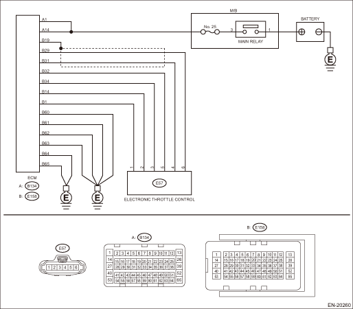
DTC DETECTING CONDITION:

Immediately at fault recognition

TROUBLE SYMPTOM:

Improper idling

Poor driving performance

CAUTION:

After servicing or replacing faulty parts, perform Clear Memory Mode Clear Memory Mode > OPERATION, and Inspection Mode Inspection Mode > PROCEDURE.

WIRING DIAGRAM:

Engine Electrical System ENGINE TYPE EZ (WITHOUT PUSH BUTTON START) Engine Electrical System > WIRING DIAGRAM

Engine Electrical System ENGINE TYPE EZ (WITH PUSH BUTTON START) Engine Electrical System > WIRING DIAGRAM

STEPCHECKYESNO

1.CHECK INPUT VOLTAGE OF ECM.

1) Turn the ignition switch to ON.

2) Measure the voltage between ECM connector and chassis ground.

Connector & terminal

(B134) No. 1 (+) — Chassis ground (−):

(B134) No. 14 (+) — Chassis ground (−):

Is the voltage 10 — 13 V-

Diagnostic Procedure with Diagnostic Trouble Code (DTC) > DTC P0606 CONTROL MODULE PROCESSOR

Repair the open or short to ground in the power supply circuit.

2.CHECK INPUT VOLTAGE OF ECM.

1) Start the engine.

2) Measure the voltage between ECM connector and chassis ground.

Connector & terminal

(B134) No. 1 (+) — Chassis ground (−):

(B134) No. 14 (+) — Chassis ground (−):

Is the voltage 13 — 15 V-

Diagnostic Procedure with Diagnostic Trouble Code (DTC) > DTC P0606 CONTROL MODULE PROCESSOR

Repair the open or short to ground in the power supply circuit.

3.CHECK HARNESS BETWEEN ECM AND ELECTRONIC THROTTLE CONTROL.

1) Turn the ignition switch to OFF.

2) Disconnect the connectors from ECM and electronic throttle control.

3) Measure the resistance of harness between ECM connector and electronic throttle control connector.

Connector & terminal

(E158) No. 32 — (E57) No. 5:

(E158) No. 34 — (E57) No. 3:

Is the resistance less than 1 --

Diagnostic Procedure with Diagnostic Trouble Code (DTC) > DTC P0606 CONTROL MODULE PROCESSOR

Repair the open circuit of harness between ECM connector and electronic throttle control connector.

4.CHECK ECM GROUND HARNESS.

1) Connect all connectors.

2) Turn the ignition switch to ON.

3) Measure the voltage between ECM connector and chassis ground.

Connector & terminal

(E158) No. 60 (+) — Chassis ground (−):

(E158) No. 61 (+) — Chassis ground (−):

(E158) No. 62 (+) — Chassis ground (−):

(E158) No. 63 (+) — Chassis ground (−):

(E158) No. 64 (+) — Chassis ground (−):

(E158) No. 65 (+) — Chassis ground (−):

Is the voltage less than 1 V-

Check the connector for poor contact and check the harness. Replace the ECM if no fault is found. Engine Control Module (ECM)

Repair the harness and connector.

NOTE:

In this case, repair the following item:

Open circuit in ground circuit

Loose engine ground terminal

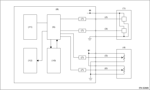
1. OUTLINE OF DIAGNOSIS

Judge as NG when the CPU operation is abnormal.

(1) Instruction check

(2) Software flow check

(3) Software monitor check

(4) If the output IC operation is abnormal

(5) CAN register check

2. COMPONENT DESCRIPTION

(1)

Throttle position sensor

(5)

Accelerator pedal position sensor 1

(9)

CPU

(2)

Throttle position sensor 1

(6)

Accelerator pedal position sensor 2

(10)

Monitoring IC

(3)

Throttle position sensor 2

(7)

I/F circuit

(11)

EEPROM

(4)

Accelerator pedal position sensor

(8)

Engine control module (ECM)

(12)

Output IC

3. EXECUTION CONDITION

Secondary Parameters

Execution condition

(1) — 1 Initial routine

(1) — 2 Ignition switch

ON

(1) — 2 Battery voltage

≥ 6.2 V

(1) — 2 Electronic throttle control relay

ON

(2) Ignition switch

ON

(3) Ignition switch

ON

(3) Battery voltage

≥ 6.2 V

(3) Electronic throttle control relay

ON

(4) Ignition switch

ON

(5) Initial routine

4. GENERAL DRIVING CYCLE

Always perform the diagnosis continuously.

5. DIAGNOSTIC METHOD

Judge as NG when the following conditions are established.

Judgment Value

Malfunction Criteria

Threshold Value

(1) — 1 Instruction value

Different from expected value

(1) — 2 Calculated result from CPU and FPU

Different from expected value

(2) Process flow result

The result and expected value do not match.

(3) High integrated IC motor continuity cut demand

Exist

(4) Communication between output driver ICs

Communication failure

(5) Writing value to CAN register

≠ Read out value

Time Needed for Diagnosis:

(1) — 1:2 time(s)

(1) — 2:512 ms

(2): 504 ms

(3): 48 ms

(4): 2500 ms

(5): Less than 1 second

Malfunction Indicator Light Illumination: Illuminates as soon as a malfunction occurs.

Dtc p060a internal control module monitoring processor performance
NOTE:For the diagnostic procedure, refer to DTC P0606. Diagnostic Procedure with Diagnostic Trouble Code (DTC) > DTC P0606 CONTROL MODULE PROCESSOR1. OUTLINE OF DIAGNOSISJudge as NG when the monitori ...

Dtc p0605 internal control module read only memory (rom) error
NOTE:For the diagnostic procedure, refer to DTC P0606. Diagnostic Procedure with Diagnostic Trouble Code (DTC) > DTC P0606 CONTROL MODULE PROCESSOR1. OUTLINE OF DIAGNOSISJudge as NG when SUM value of ...

Other materials:

Eyesight system wiring diagram
...

© 2017-2024 Copyright www.sulegacy.com