Subaru Legacy BN/BS (2015-2019) Service Manual: Dtc p0851 park/neutral switch input circuit low
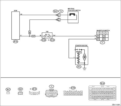
DTC DETECTING CONDITION: Detected when two consecutive driving cycles with fault occur. TROUBLE SYMPTOM: Improper idling CAUTION: After servicing or replacing faulty parts, perform Clear Memory Mode Clear Memory Mode > OPERATION, and Inspection Mode Inspection Mode > PROCEDURE. 1. CVT MODEL WIRING DIAGRAM: Engine Electrical System Engine Electrical System > WIRING DIAGRAM • Engine Electrical System ENGINE TYPE FB (WITHOUT PUSH BUTTON START) Engine Electrical System > WIRING DIAGRAM • Engine Electrical System ENGINE TYPE FB (WITH PUSH BUTTON START) Engine Electrical System > WIRING DIAGRAM
2. OUTLINE OF DIAGNOSIS Detect the open or short circuit of neutral SW. Judge as NG when the ECM neutral terminal input differs from the reception data from TCM. 3. EXECUTION CONDITION
4. GENERAL DRIVING CYCLE Perform the diagnosis only once after the enable conditions have been established. 5. DIAGNOSTIC METHOD If the duration of time while the following conditions are met is longer than the time indicated, judge as NG.
Time Needed for Diagnosis: 64 ms - 100 time(s) Malfunction Indicator Light Illumination: Illuminates when malfunction occurs in 2 continuous driving cycles. 6. MT MODEL WIRING DIAGRAM: • Engine Electrical System ENGINE TYPE FB (WITHOUT PUSH BUTTON START) Engine Electrical System > WIRING DIAGRAM • Engine Electrical System ENGINE TYPE FB (WITH PUSH BUTTON START) Engine Electrical System > WIRING DIAGRAM
7. OUTLINE OF DIAGNOSIS Detect the open or short circuit of neutral SW. Judge as NG when there is no change in the neutral SW even if the driving shift was applied. (There is neutral SW ON/OFF inversion from the vehicle speed and engine speed.) 8. EXECUTION CONDITION
9. GENERAL DRIVING CYCLE Perform the diagnosis continuously after the enable conditions have been established. 10. DIAGNOSTIC METHOD Judge NG when the malfunction criteria below are completed determined times or more after the neutral SW change.
Time Needed for Diagnosis: 3 time(s) Malfunction Indicator Light Illumination: Illuminates when malfunction occurs in 2 continuous driving cycles. |
 Dtc p0128 coolant thermostat (engine coolant temperature below thermostat regulating temperature)
DTC DETECTING CONDITION:Detected when two consecutive driving cycles with fault occur.TROUBLE SYMPTOM:Thermostat remains open.CAUTION:After servicing or replacing faulty parts, perform Clear Memory Mo ...
 Dtc u0073 control module communication bus off
NOTE:For the diagnostic procedure, refer to LAN section. Basic Diagnostic Procedure1. OUTLINE OF DIAGNOSISDetect malfunction of CAN communication.Judge as NG when CAN communication failure has occurr ...
Other materials:
General diagnostic table inspection
NOTE:Vibration while cruising may be caused by an unbalanced tire, improper tire inflation pressure, improper wheel alignment, etc.SymptomsPossible causeCorrective actionNoise or vibration from propeller shaft• Center bearing• Runout of propeller shaft• Loose or gap at connectionsI ...
