DTC DETECTING CONDITION: Detected when two consecutive driving cycles with fault occur. TROUBLE SYMPTOM: Improper idling CAUTION: After servicing or replacing faulty parts, perform Clear Memory Mode Clear Memory Mode > OPERATION, and Inspection Mode Inspection Mode > PROCEDURE. 1. CVT MODEL WIRING DIAGRAM: • Engine Electrical System ENGINE TYPE FB (WITHOUT PUSH BUTTON START) Engine Electrical System > WIRING DIAGRAM • Engine Electrical System ENGINE TYPE FB (WITH PUSH BUTTON START) Engine Electrical System > WIRING DIAGRAM 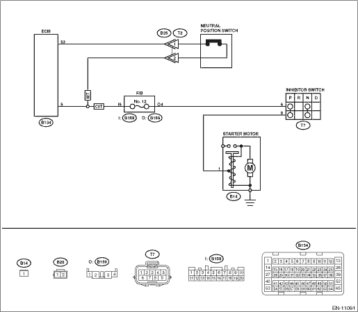
| STEP | CHECK | YES | NO | | Is there any fault in select cable- | Repair or adjust the select cable. Select Cable | Diagnostic Procedure with Diagnostic Trouble Code (DTC) > DTC P0852 PARK/NEUTRAL SWITCH INPUT CIRCUIT HIGH | 2.CHECK INPUT SIGNAL OF ECM. 1) Turn the ignition switch to ON. 2) Measure the voltage between ECM and chassis ground with select lever at “P” range and “N” range. Connector & terminal (B134) No. 5 (+) — Chassis ground (−): | Is the voltage less than 1 V- | Repair the poor contact of ECM connector. | Diagnostic Procedure with Diagnostic Trouble Code (DTC) > DTC P0852 PARK/NEUTRAL SWITCH INPUT CIRCUIT HIGH | 3.CHECK HARNESS BETWEEN ECM AND INHIBITOR SWITCH CONNECTOR. 1) Turn the ignition switch to OFF. 2) Disconnect the connectors from ECM and inhibitor switch. 3) Measure the resistance of harness between ECM connector and inhibitor switch connector. Connector & terminal (B134) No. 5 — (T7) No. 6: | Is the resistance less than 1 -- | Diagnostic Procedure with Diagnostic Trouble Code (DTC) > DTC P0852 PARK/NEUTRAL SWITCH INPUT CIRCUIT HIGH | Repair the harness and connector. NOTE: In this case, repair the following item: • Open circuit in harness between ECM connector and inhibitor switch connector • Poor contact of coupling connector | 4.CHECK INHIBITOR SWITCH GROUND LINE. Measure the resistance of harness between inhibitor switch connector and engine ground. Connector & terminal (T7) No. 9 — Engine ground: | Is the resistance less than 5 -- | Replace the inhibitor switch. Inhibitor Switch | Repair the harness and connector. NOTE: In this case, repair the following item: • Open circuit of harness between inhibitor switch connector and starter motor ground line • Poor contact of coupling connector • Poor contact of starter motor connector • Poor contact of starter motor ground • Starter motor |
2. OUTLINE OF DIAGNOSIS Detect the open or short circuit of neutral SW. Judge as NG when the ECM neutral terminal input differs from the reception data from TCM. 3. EXECUTION CONDITION Secondary Parameters | Execution condition | Battery voltage | ≥ 10.9 V | Starter relay feedback voltage | < Battery voltage - 0.35 | Data received from TCM | = “P” range/“N” range |
4. GENERAL DRIVING CYCLE Perform the diagnosis only once after the enable conditions have been established. 5. DIAGNOSTIC METHOD If the duration of time while the following conditions are met is longer than the time indicated, judge as NG. Judgment ValueMalfunction Criteria | Threshold Value | Voltage of the neutral position switch signal | ≥ Battery voltage - 0.6 | Time Needed for Diagnosis: 64 ms - 100 time(s) Malfunction Indicator Light Illumination: Illuminates when malfunction occurs in 2 continuous driving cycles. 6. MT MODEL WIRING DIAGRAM: • Engine Electrical System ENGINE TYPE FB (WITHOUT PUSH BUTTON START) Engine Electrical System > WIRING DIAGRAM • Engine Electrical System ENGINE TYPE FB (WITH PUSH BUTTON START) Engine Electrical System > WIRING DIAGRAM
| STEP | CHECK | YES | NO | 1.CHECK INPUT SIGNAL OF ECM. 1) Turn the ignition switch to ON. 2) Place the shift lever in neutral. 3) Measure the voltage between ECM connector and chassis ground. Connector & terminal (B134) No. 5 (+) — Chassis ground (−): | Is the voltage less than 1 V- | Repair the poor contact of ECM connector. | Diagnostic Procedure with Diagnostic Trouble Code (DTC) > DTC P0852 PARK/NEUTRAL SWITCH INPUT CIRCUIT HIGH | 2.CHECK HARNESS BETWEEN ECM AND NEUTRAL POSITION SWITCH CONNECTOR. 1) Turn the ignition switch to OFF. 2) Disconnect the connectors from ECM and neutral position switch. 3) Measure the resistance of harness between ECM connector and neutral position switch connector. Connector & terminal (B134) No. 5 — (B25) No. 2: (B134) No. 53 — (B25) No. 1: | Is the resistance less than 1 -- | Diagnostic Procedure with Diagnostic Trouble Code (DTC) > DTC P0852 PARK/NEUTRAL SWITCH INPUT CIRCUIT HIGH | Repair the harness and connector. NOTE: In this case, repair the following item: • Open circuit in harness between ECM connector and neutral position switch connector • Poor contact of coupling connector | 3.CHECK NEUTRAL POSITION SWITCH. 1) Place the shift lever in neutral. 2) Measure the resistance between neutral position switch terminals. | Is the resistance less than 1 -- | Repair the poor contact of neutral position switch connector. | Replace the neutral position switch. Switches and Harness |
7. OUTLINE OF DIAGNOSIS Detect the open or short circuit of neutral SW. Judge as NG when there is no change in the neutral SW even if the driving shift was applied. (There is neutral SW ON/OFF inversion from the vehicle speed and engine speed.) 8. EXECUTION CONDITION Secondary Parameters | Execution condition | Battery voltage | ≥ 10.9 V | The number of driving condition change from a) to b) a) Vehicle speed & Engine speed | = 3 time(s) ≤ 0 km/h (0 MPH) ≥ 550 rpm and ≤ 900 rpm | b) Vehicle speed & Engine speed | ≥ 64 km/h (39.8 MPH) ≥ 1500 rpm and ≤ 2150 rpm |
9. GENERAL DRIVING CYCLE Perform the diagnosis continuously after the enable conditions have been established. 10. DIAGNOSTIC METHOD Judge NG when the malfunction criteria below are completed determined times or more after the neutral SW change. Judgment ValueMalfunction Criteria | Threshold Value | Neutral switch output voltage | ≥ Battery voltage - 0.6 V | Time Needed for Diagnosis: 3 time(s) Malfunction Indicator Light Illumination: Illuminates when malfunction occurs in 2 continuous driving cycles. |  Dtc p059a active grille air shutter "a" position sensor circuit
