Subaru Legacy BN/BS (2015-2019) Service Manual: Dtc p2103 throttle actuator "a" control motor circuit high
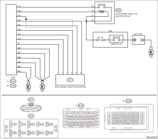
DTC DETECTING CONDITION: Immediately at fault recognition CAUTION: After servicing or replacing faulty parts, perform Clear Memory Mode Clear Memory Mode > OPERATION, and Inspection Mode Inspection Mode > PROCEDURE. WIRING DIAGRAM: • Engine Electrical System ENGINE TYPE EZ (WITHOUT PUSH BUTTON START) Engine Electrical System > WIRING DIAGRAM • Engine Electrical System ENGINE TYPE EZ (WITH PUSH BUTTON START) Engine Electrical System > WIRING DIAGRAM
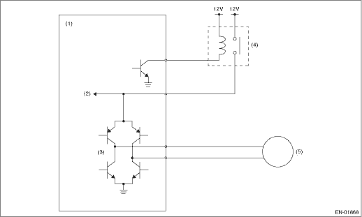
1. OUTLINE OF DIAGNOSIS Judge as NG when the electronic throttle control power is supplied even when ECM sets the electronic throttle control relay to OFF. 2. COMPONENT DESCRIPTION
3. EXECUTION CONDITION
4. GENERAL DRIVING CYCLE • When ignition switch ON > OFF • Ignition switch OFF > ON (Only after clearing memory) 5. DIAGNOSTIC METHOD If the duration of time while the following conditions are met is longer than the time indicated, judge as NG.
Time Needed for Diagnosis: 600 ms Malfunction Indicator Light Illumination: Illuminates as soon as a malfunction occurs. |
 Dtc p2109 throttle/pedal position sensor "a" minimum stop performance
NOTE:For the diagnostic procedure, refer to DTC P2101. Diagnostic Procedure with Diagnostic Trouble Code (DTC) > DTC P2101 THROTTLE ACTUATOR "A" CONTROL MOTOR CIRCUIT RANGE/PERFORMANCE1. OUTLINE OF D ...
 Dtc p2102 throttle actuator "a" control motor circuit low
DTC DETECTING CONDITION:Immediately at fault recognitionTROUBLE SYMPTOM:• Improper idling• Poor driving performance• Engine stalls.CAUTION:After servicing or replacing faulty parts, ...
Other materials:
Installation
1. SEDAN MODELCAUTION:Before installing the bumper face, match the claws on the bracket - rear bumper with the engaging position of flange section on the bumper face side. If the engaging position is not correct, the flange section may be broken or the clearance between fender panel and bumper face ...
