Subaru Legacy BN/BS (2015-2019) Service Manual: Dtc p2127 throttle/pedal position sensor/switch "e" circuit low
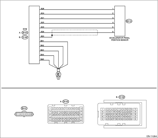
DTC DETECTING CONDITION: Immediately at fault recognition TROUBLE SYMPTOM: • Improper idling • Poor driving performance CAUTION: After servicing or replacing faulty parts, perform Clear Memory Mode Clear Memory Mode > OPERATION, and Inspection Mode Inspection Mode > PROCEDURE. WIRING DIAGRAM: • Engine Electrical System ENGINE TYPE FB (WITHOUT PUSH BUTTON START) Engine Electrical System > WIRING DIAGRAM • Engine Electrical System ENGINE TYPE FB (WITH PUSH BUTTON START) Engine Electrical System > WIRING DIAGRAM
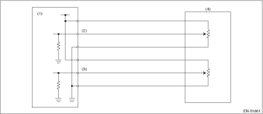
1. OUTLINE OF DIAGNOSIS Detect the open or short circuit of accelerator pedal position sensor 2. Judge as NG if out of specification. 2. COMPONENT DESCRIPTION
3. EXECUTION CONDITION
4. GENERAL DRIVING CYCLE Always perform the diagnosis continuously. 5. DIAGNOSTIC METHOD If the duration of time while the following conditions are met is longer than the time indicated, judge as NG.
Time Needed for Diagnosis: 100 ms Malfunction Indicator Light Illumination: Illuminates as soon as a malfunction occurs. |
 Dtc p2128 throttle/pedal position sensor/switch "e" circuit high
DTC DETECTING CONDITION:Immediately at fault recognitionTROUBLE SYMPTOM:• Improper idling• Poor driving performanceCAUTION:After servicing or replacing faulty parts, perform Clear Memory M ...
 Dtc p2123 throttle/pedal position sensor/switch "d" circuit high
DTC DETECTING CONDITION:Immediately at fault recognitionTROUBLE SYMPTOM:• Improper idling• Poor driving performanceCAUTION:After servicing or replacing faulty parts, perform Clear Memory M ...
Other materials:
Dtc p059a active grille air shutter "a" position sensor circuit
DTC DETECTING CONDITION:Immediately at fault recognitionCAUTION:After servicing or replacing faulty parts, perform Clear Memory Mode Clear Memory Mode > OPERATION, and Inspection Mode Inspection Mode > PROCEDURE.STEPCHECKYESNO1.CHECK ACTIVE GRILLE SHUTTER.Check the area around the active grille sh ...
