Honda Civic manuals

Subaru Legacy BN/BS (2015-2019) Service Manual: Electrical specification
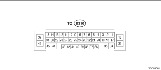
NOTE:

Terminal numbers in VDCCM&H/U connector (on the control module side) are shown in the figure.

When the connector is removed from the VDCCM&H/U, the brake warning light (EBD warning light), ABS warning light, VDC warning light & VDC indicator light, VDC OFF indicator light, and the hill hold indicator light illuminate.

Content

Terminal No.

(+) — (−)

Input/Output signal

Measured value and measuring conditions

Power supply

5 — 46

10 — 15 V when the ignition switch is ON.

ABS wheel speed sensor

Front LH wheel

Power supply

41 — 46

0 — 18 V when the ignition switch is ON.

Signal

40

7 — 14 mA: Rectangle waveform

Front RH wheel

Power supply

37 — 46

0 — 18 V when the ignition switch is ON.

Signal

36

7 — 14 mA: Rectangle waveform

Rear LH wheel

Power supply

39 — 46

0 — 18 V when the ignition switch is ON.

Signal

38

7 — 14 mA: Rectangle waveform

Rear RH wheel

Power supply

43 — 46

0 — 18 V when the ignition switch is ON.

Signal

42

7 — 14 mA: Rectangle waveform

Valve relay power supply

16 — 46

10 — 15 V

Motor relay power supply

33 — 46

10 — 15 V

Stop light switch

17 — 46

1.5 V or less when the stop light is OFF; 10 — 15 V when the stop light is ON.

Brake light relay power supply

27 — 46

10 — 15 V when the ignition switch is ON.

Vehicle speed output signal

24

0 ←> 12 V pulse

VDC OFF switch

1 — 46

1 - or less when the OFF switch is “ON”; 1 M- or more when the switch is “OFF”.

Parking brake switch

19

Pulse signal

Parking brake switch

20

Pulse signal

Parking brake switch

21

Pulse signal

Parking brake switch

26

Pulse signal

Rear brake caliper RH

34 — 35

Pulse signal

Rear brake caliper LH

44 — 45

Pulse signal

Hill hold switch

6 — 46

10 — 15 V when the hill hold switch is ON.

Parking brake indicator light

3 — 46

0 V when the light is on; 10 — 15 V when the light is off.

Brake fluid level switch

8 — 46

10 — 15 V when the ignition switch is ON.

Clutch stroke sensor power supply

11 — 15

4.8 — 5.2 V

Clutch stroke sensor ground

15

Clutch stroke sensor signal

10

Pulse signal

CAN communication line (H)

12

Pulse signal

CAN communication line (L)

13

Pulse signal

Ground

46

Wiring diagram
Refer to “Vehicle Dynamics Control System” in the wiring diagram. Vehicle Dynamics Control System ...

Diagnostic procedure with diagnostic trouble code (dtc)
...

Other materials:

Read diagnostic trouble code (dtc) operation
1. On «Start» display, select «Diagnosis».2. On «Vehicle selection» display, input the target vehicle information and select «Confirmed».3. On «Main Menu» display, select «Each System».4. On «Select System» display, select «Infotainment» and select «Enter».5. On «Select Function» ...

© 2017-2024 Copyright www.sulegacy.com